Method for driving an internal-combustion engine and an internal-combustion engine

a technology of combustion engine and combustion engine, which is applied in the direction of machines/engines, output power, electric control, etc., can solve the problems increase the complexity of the turbine, and affect the efficiency of the turbo compressor, so as to improve the exhaust gas delivery and solve the problem of small exhaust gas flow

Inactive Publication Date: 2003-01-02
SAAB AUTOMOBILE AB
View PDF0 Cites 65 Cited by
  • Summary
  • Abstract
  • Description
  • Claims
  • Application Information

AI Technical Summary

Benefits of technology

[0006] The object of the invention is to achieve an improved exhaust-gas delivery to the exhaust-gas turbine. Another object is to achieve a simple solution.

Problems solved by technology

This means, however, that at lower revs and with smaller exhaust-gas flows, exhaust-gas energy is lost en route to the exhaust-gas turbine, thereby impairing the effectiveness of the turbo compressor.
This creates disadvantages, however, in respect of high exhaust-gas flows, since the small dimensions result in a throttling of the exhaust-gas flow and high counter-pressure in the exhaust-gas pipe, with accompanying air-supply problems.
In order to obtain the required adjustability, there is a waste gate valve disposed in each inlet, which adds to the complexity of the turbine.
The two inlet ducts to the exhaust-gas turbine here have the same sizes, designed for a large exhaust-gas flow, with accompanying loss of efficiency at low revs and small exhaust-gas flows.

Method used


Image

  • Method for driving an internal-combustion engine and an internal-combustion engine
  • Method for driving an internal-combustion engine and an internal-combustion engine
  • Method for driving an internal-combustion engine and an internal-combustion engine

Examples


Embodiment Construction

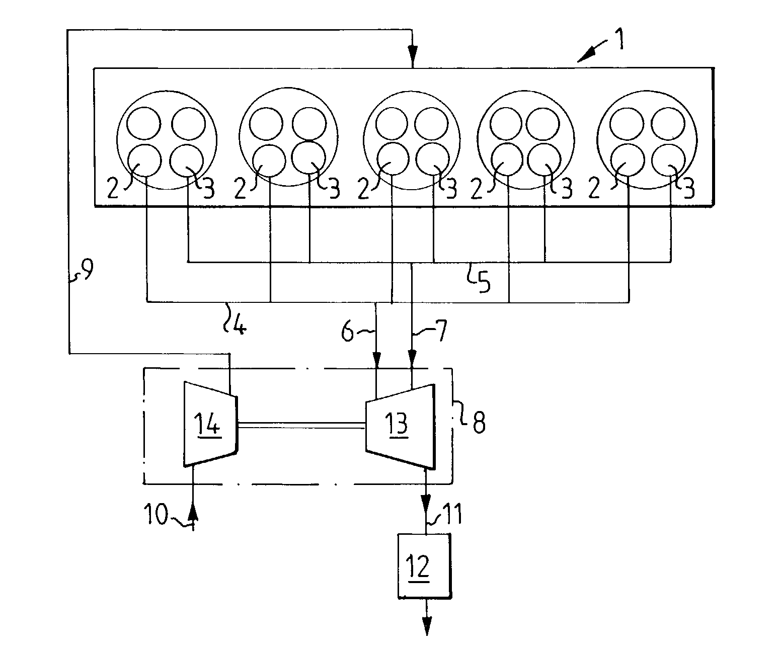
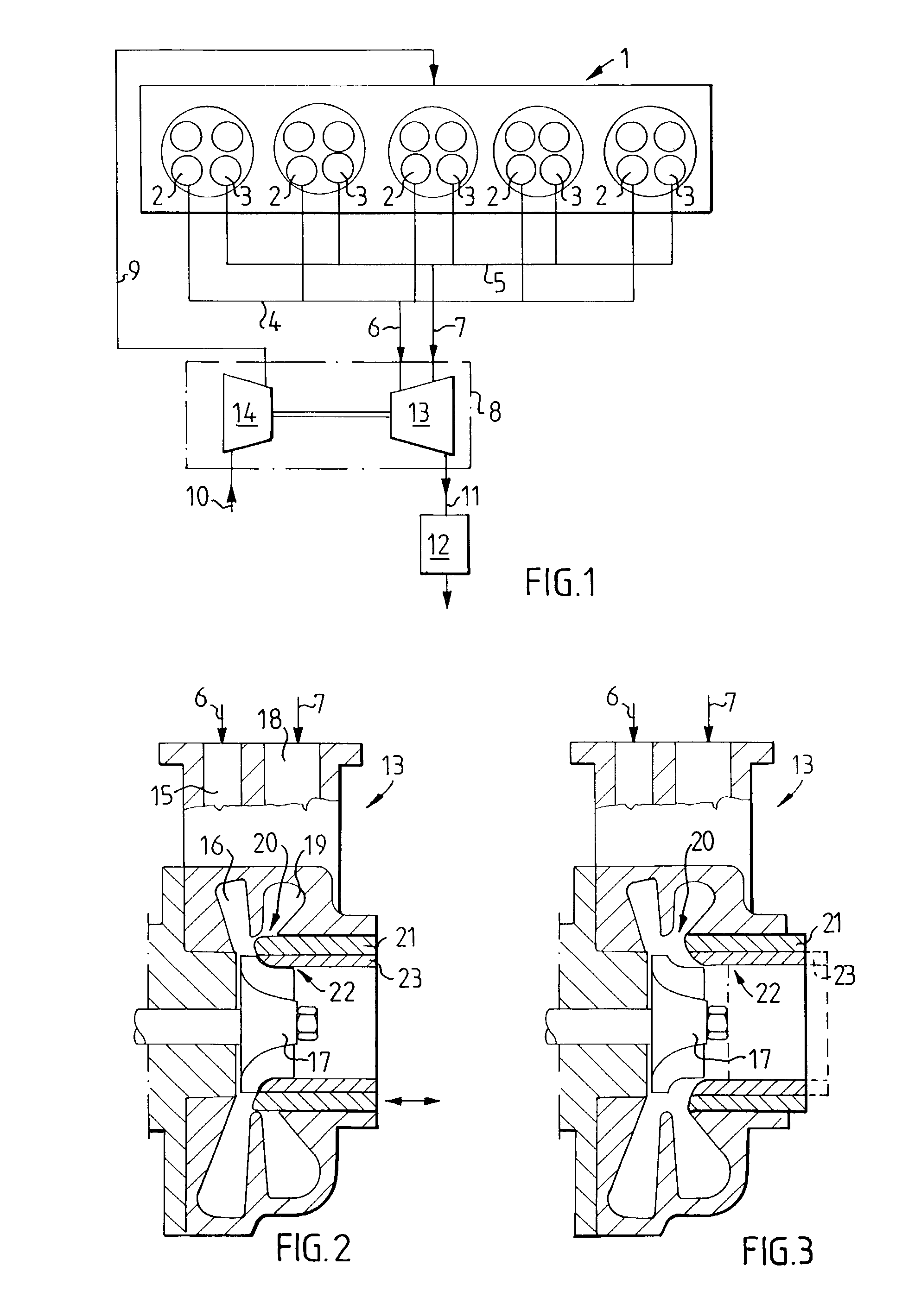
[0018] FIG. 1 shows in diagrammatic representation an Otto-type multi-cylinder internal-combustion engine 1 realized according to the invention. The engine cylinders each have at least two exhaust-gas valves 2, 3, in which a first exhaust-gas valve 2 in each cylinder is connected to a first exhaust manifold 4, and in which a second exhaust-gas valve 3 in each cylinder is connected to a second exhaust manifold 5. The two exhaust manifolds 4, 5 emerge via respectively a first exhaust-gas pipe 6 and a second exhaust-gas pipe 7 into a supercharger 8, by means of which charge air is fed to the engine 1 via an air pipe 9 in a known manner (not shown here in greater detail). The supercharger 8 driven by exhaust gases from the engine is provided with air via an inlet 10 and has an exhaust-gas outlet 11 intended for the exhaust gases, whence the exhaust gases are led away from the engine in the conventional manner via a catalyser 12 and other conventional components (not shown here in greate...


PUM


Abstract

In an internal-combustion engine having an exhaust-gas driven supercharger (8) and having at least two exhaust-gas valves (2, 3) per cylinder, a first exhaust-gas valve (2) in each cylinder is connected to a first exhaust manifold (4), whilst a second exhaust-gas valve (3) in each cylinder is connected to a second exhaust manifold (5). The two exhaust manifolds (4, 5) lead to at least one exhaust-gas turbine in at least one turbo compressor and the first exhaust-gas valves (2) are arranged to be opened at all engine speeds, whilst the second exhaust-gas valves (3) are arranged to be opened only at higher engine speeds. The first exhaust manifold (4) has a smaller flow area than the second exhaust manifold (5). By choosing which exhaust-gas valves are to be used, the size of the flow ducts between engine and exhaust-gas turbine can easily be suited to the size of the exhaust-gas flow which is available at the time.

Description

[0001] The invention relates firstly to a method for driving an internal-combustion engine, according to the preamble of Patent claim 1, and secondly to an internal-combustion engine, according to the preamble of Patent claim 5.PRIOR ART[0002] In turbo engines having an exhaust-gas-driven turbo compressor, the performance of the engine is largely dependent on the working range of the turbo compressor. The exhaust-gas turbine of the turbo compressor and the exhaust-gas ducts leading thereto are usually dimensioned for the high exhaust-gas flows which are generated at high revs and high engine loads. This means, however, that at lower revs and with smaller exhaust-gas flows, exhaust-gas energy is lost en route to the exhaust-gas turbine, thereby impairing the effectiveness of the turbo compressor.[0003] In order to be able to achieve good performance of the turbo compressor at low revs, it is desirable to use a small turbine and small dimensions on the pipes thereto with a view to red...

Claims


Application Information

Patent Timeline
Patent Type & Authority Applications(United States)
IPC IPC(8): F01N13/10F02B37/007F02B37/02F02B37/18F02B37/22F02B39/00F02D13/02F02D23/00F02D41/00
CPCF01D17/143F01N13/107F02B37/007F02B37/02F02B37/025F02B37/18F05D2220/40F02D13/0257F02D23/00F02D2041/001Y02T10/18Y02T10/144F02B37/22Y02T10/12
Inventor DRANGEL, HANSKARLSSON, HANSLARSEN, ANDERSNORDIN, HENRIK
Owner SAAB AUTOMOBILE AB
Why Eureka
Try Eureka