Torque shearing nut system and method

a technology of twisting nuts and nuts, which is applied in the direction of screw, load-modified fasteners, fastening means, etc., can solve the problems of limiting the torque that can be applied to the bolt, and the cost of implementing the friction fitting assembly method, so as to reduce weight and shipping costs, and reduce the number of manufacturing cycles

Inactive Publication Date: 2003-01-02
JAMESON MATTHEW HARVEY
View PDF5 Cites 14 Cited by
  • Summary
  • Abstract
  • Description
  • Claims
  • Application Information

AI Technical Summary

Benefits of technology

0038] (4) To reduce the number of manufacturing cycles necessary to produce twistnuts.
0039] (5) To enable production of twistnuts without expensive and high maintenance Hatebur (or equivalent) hot forging machines.
0040] (6) To reduce the weight and shipping costs associated with existing twistnuts by using a lighter material for twistnut construction, as well as reduce the energy requirements necessary to ship large quantities of these items via truck or other transport means.
0041] (7) To reduce the capital equipment costs of producing twistnuts by eliminating the need for expensive hot forging equipment.
0042] (8) To eliminate the energy requirements associated with hot forging equipment required to produce prior art twistnuts.

Problems solved by technology

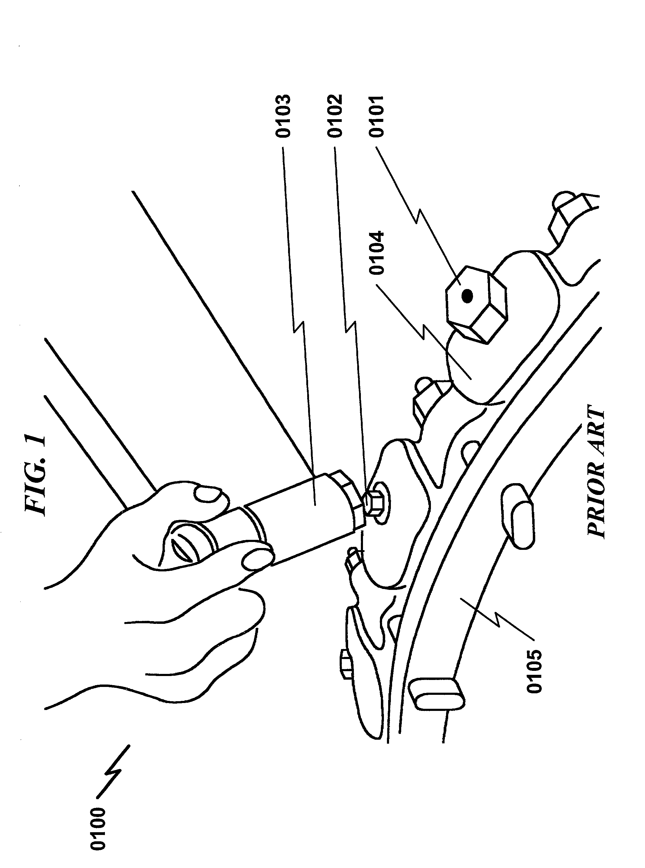
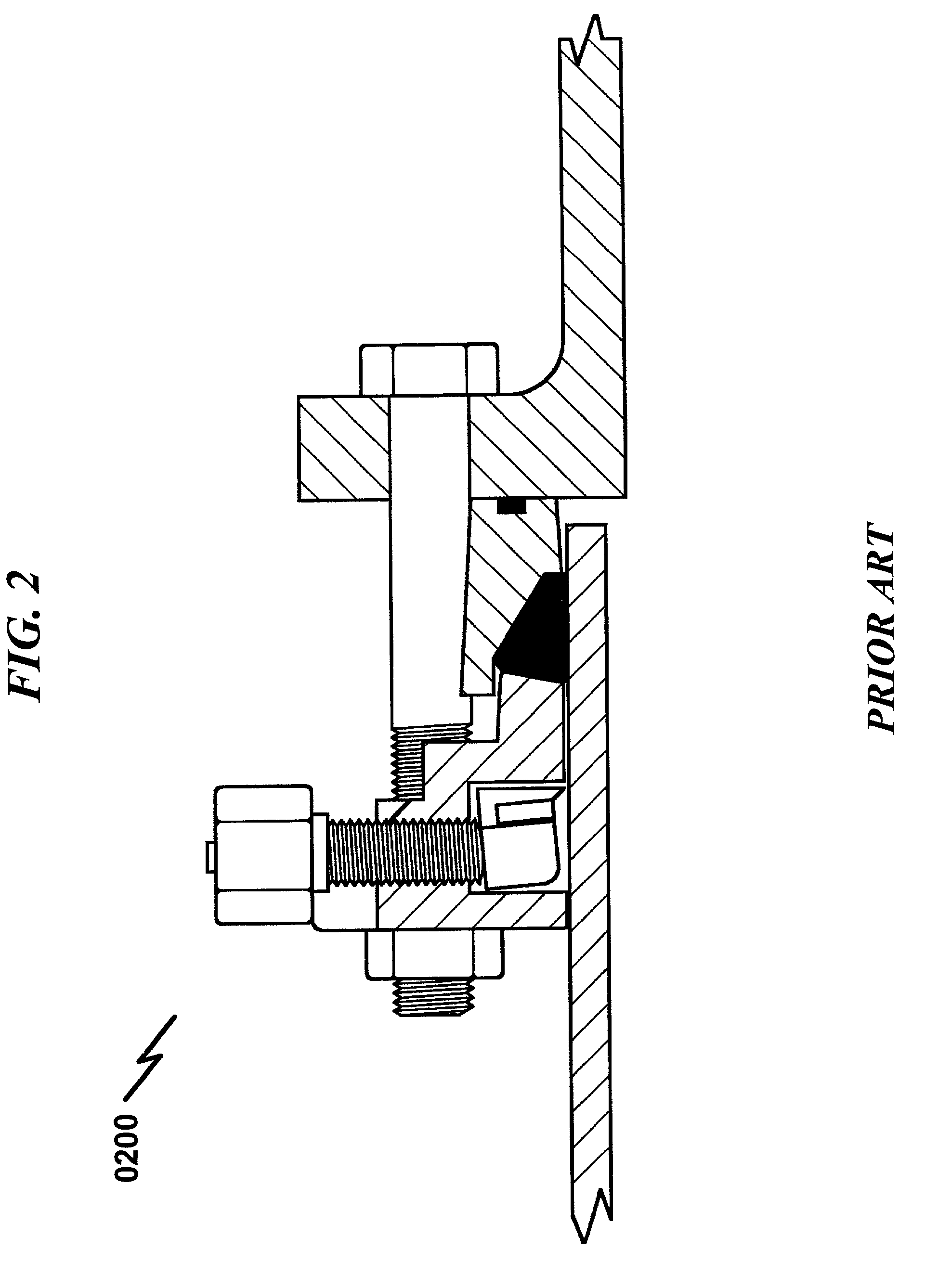
The specific purpose of these "twistnuts" is to shear off specially designed axial torque limiting members ("tangs") on the top of casted iron bolts and therefore limit the amount of torque that can be applied to the bolt by the shear-failure of the tangs.
This friction fit assembly method is expensive to implement.

Method used


Image

  • Torque shearing nut system and method
  • Torque shearing nut system and method
  • Torque shearing nut system and method

Examples


Embodiment Construction

[0087] While this invention is susceptible of embodiment in many different forms, there is shown in the drawings and will herein be described in detailed preferred embodiment of the invention with the understanding that the present disclosure is to be considered as an exemplification of the principles of the invention and is not intended to limit the broad aspect of the invention to the embodiment illustrated.

[0088] The numerous innovative teachings of the present application will be described with particular reference to the presently preferred embodiment, wherein these innovative teachings are advantageously applied to the particular problems of a TORQUE SHEARING NUT SYSTEM AND METHOD. However, it should be understood that this embodiment is only one example of the many advantageous uses of the innovative teachings herein. In general, statements made in the specification of the present application do not necessarily limit any of the various claimed inventions. Moreover, some state...


PUM


Abstract

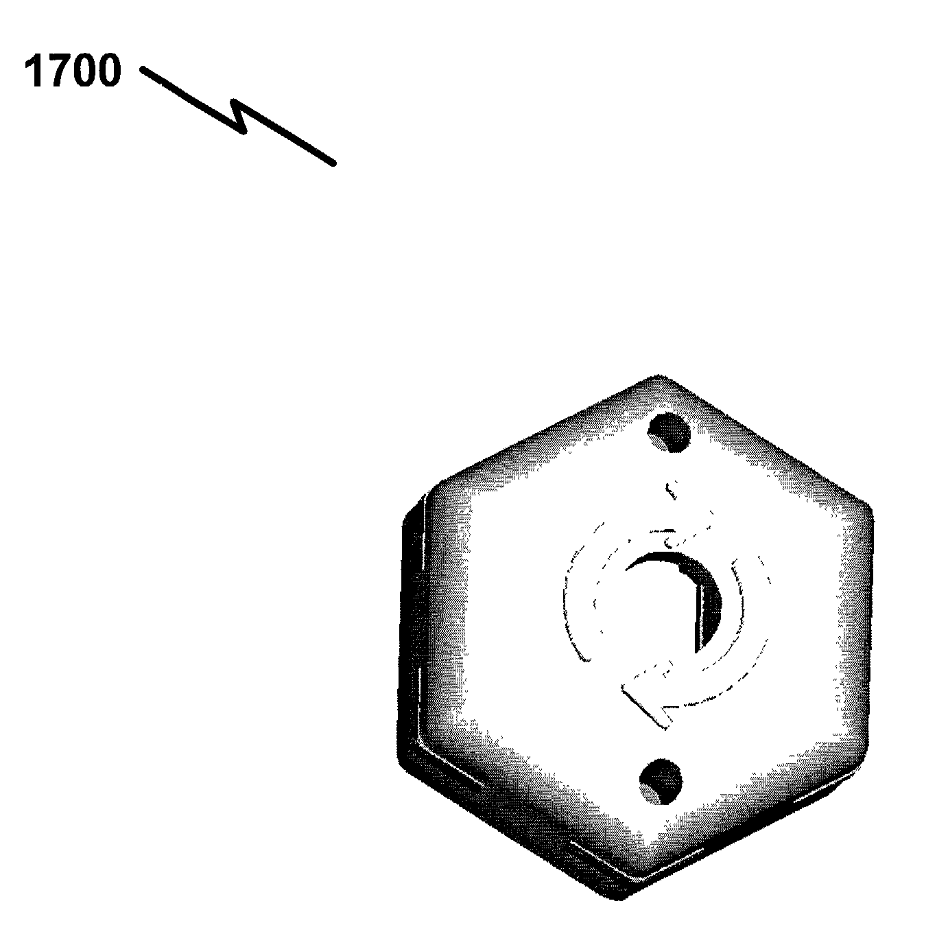
A torque shearing nut system and method incorporating a hybrid "twistnut" constructed of a metallic force bearing member and a thermoplastic rubber (Vyram(R), etc.) and/or plastic (polyamide (nylon), polypropylene (PP), etc.) surrounding support member is disclosed. The present invention permits the use of one or more steel washer inserts formed to permit shearing of an external axial element for the purposes of ensuring the application of a predefined torque to the external axial member. The primary advantage of the present invention is one of cost, in that the present invention can be manufactured using stamped steel washers that are surrounded with and impregnated with molded thermoplastic rubber (Vyram(R), etc.) and/or plastic (polyamide (nylon), polypropylene (PP), etc.). This encapsulation process is significantly less expensive than traditional hot-forging methodologies used to manufacture prior art twistnuts and the like. Furthermore, the present invention permits a reduction in the complexity of steps required to both manufacture the twistnuts as well as combine them with the external axial member. The present invention may be manufactured without the need for specialized hot forge tooling and hot forge machinery, and as such the production volume limitations of the prior art are not present in the manufacture of the present invention.

Description

Provisional Patent Applications[0001] Applicant claims benefit pursuant to 35 U.S.C. .sctn.119 and hereby incorporates by reference Provisional Patent Application for "TORQUE SHEARING NUT SYSTEM AND METHOD", S / No. 60 / 302,139, docket MHJ-2001-001, filed Jun. 30, 2001, and submitted to the USPTO with Express Mail Label EF409812974US.[0002] Applicant claims benefit pursuant to 35 U.S.C. .sctn.119 and hereby incorporates by reference Provisional Patent Application for "TORQUE SHEARING NUT SYSTEM AND METHOD", S / No. 60 / 315,127, docket MHJ-2001-002, filed Aug. 27, 2001, and submitted to the USPTO with Express Mail Label EF409812435US.[0003] Applicant claims benefit pursuant to 35 U.S.C. .sctn.119 and hereby incorporates by reference Provisional Patent Application for "TORQUE SHEARING NUT SYSTEM AND METHOD", S / No. 60 / 332,189, docket MHJ-2001-003, filed Nov. 13, 2001, and submitted to the USPTO with Express Mail Label ET702669137US.Utility Patents[0004] Applicant hereby incorporates by refer...

Claims


Application Information

Patent Timeline
Patent Type & Authority Applications(United States)
IPC IPC(8): F16B31/02
CPCF16B31/02
Inventor JAMESON, MATTHEW HARVEY
Owner JAMESON MATTHEW HARVEY
Why Eureka
Try Eureka