Door support system and method

a technology for supporting systems and doors, applied in the direction of building components, constructions, buildings, etc., can solve the problems of inability to use certain temporary door restraint devices, inconvenient installation, and inability to adjust the position of the door, etc., to achieve the effect of convenient installation and easy removal

a technology for supporting systems and doors, applied in the direction of building components, constructions, buildings, etc., can solve the problems of inability to use certain temporary door restraint devices, inconvenient installation, and inability to adjust the position of the door, etc., to achieve the effect of convenient installation and easy removal

US20030005641A1Inactive Publication Date: 2003-01-09AMERICAN INJECTION MOLDING

Image

  • Door support system and method
  • Door support system and method
  • Door support system and method

Examples


Embodiment Construction

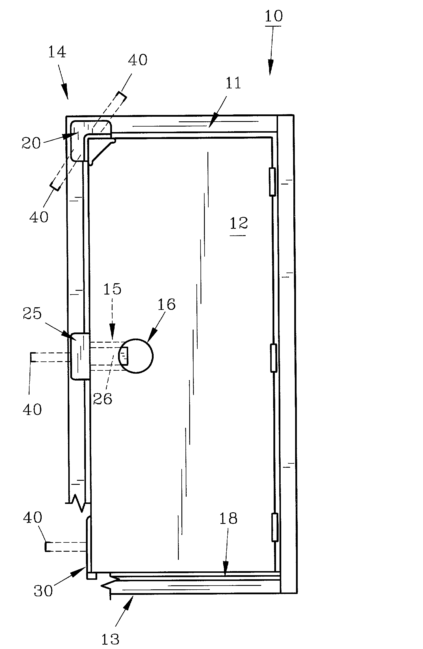
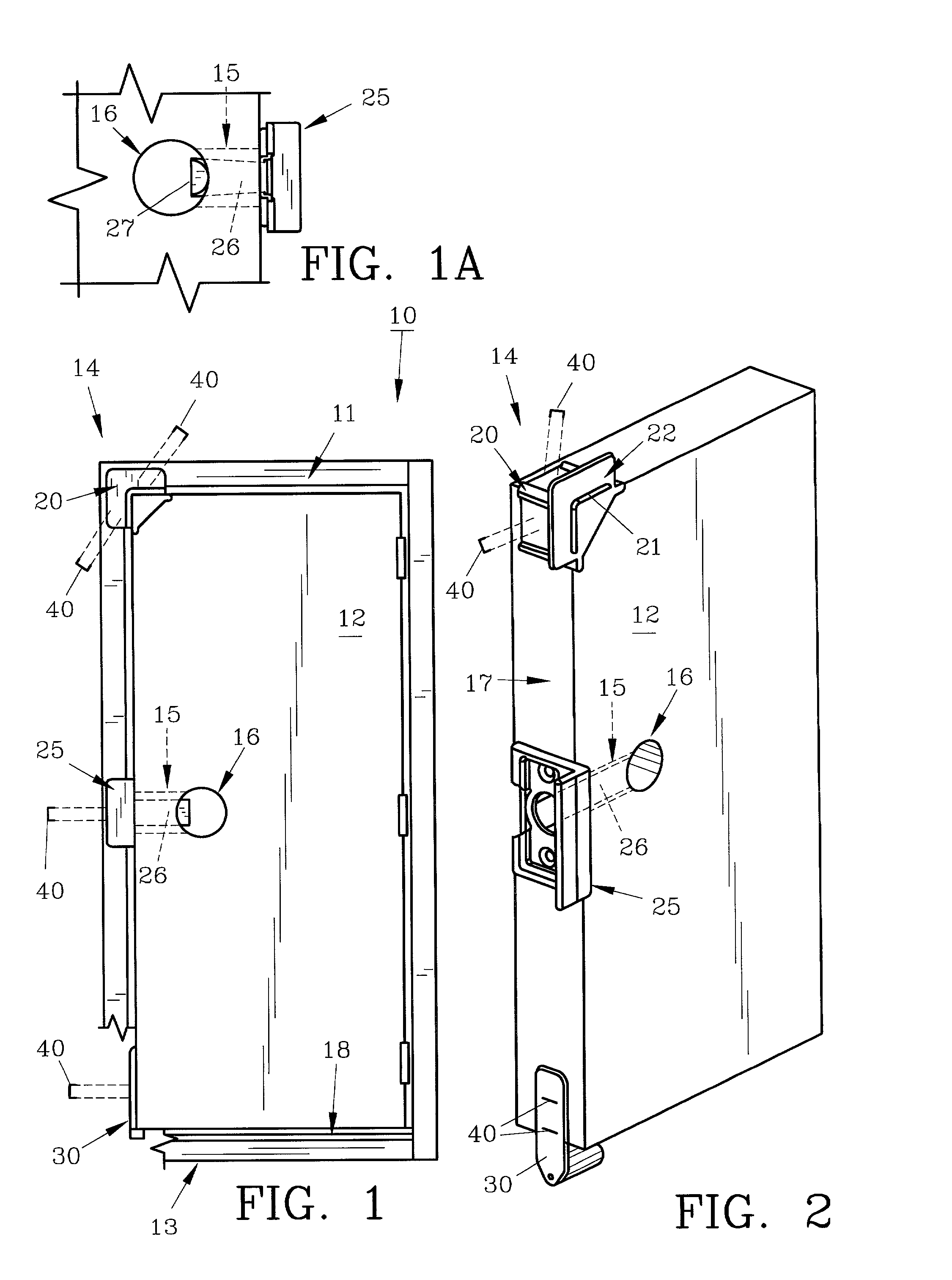
[0030] For a better understanding of the invention and its method operation, turning now to the drawings, FIG. 1 illustrates a typical pre-hung door assembly 10 including a frame 11 which is hingedly joined to door 12 with threshold 13 attached to frame 11. Frame 11 has been cut-away at the left, bottom corner for demonstrative purposes.

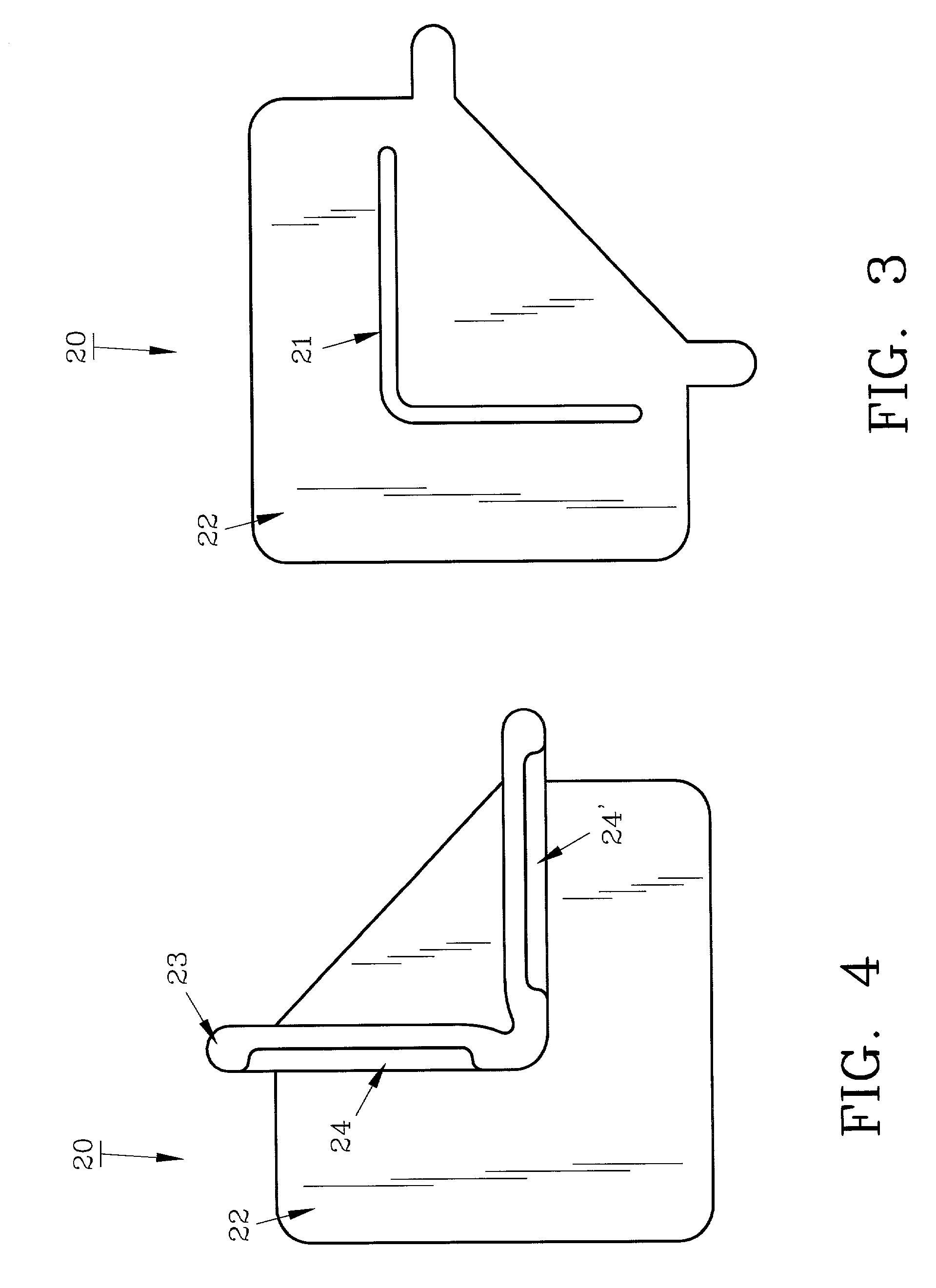
[0031] As would be understood, various types of pre-hung door assemblies are available in hardware stores, home improvement centers and the like without door hardware. Door 12 as shown is generally the exterior type and threshold 13 seen therewith. In order to safely, quickly and conveniently transport, handle and install pre-hung door assembly 10 preferred door support system 14 has been devised which includes preferred molded corner member 20, preferred retainer 25 and preferred door rest 30. Preferred door support system 14 is shown on door 12 removed from frame 11 and threshold 13 in FIG. 2. Preferred corner member 20 is positioned opposite the h...


PUM


Abstract

A door support system and method are provided for manufacturers and distributors of pre-hung door assemblies as used in homes and other buildings. The door support system includes a molded, polymeric corner member, retainer which fits within the latch throat of the door and a door rest which is positioned on the edge of the door, between the threshold and the door bottom. With the door support system installed, the pre-hung door assembly can easily be transported and installed without damage or injury, even with rough handling.

Description

[0001] The invention herein pertains to pre-hung door assemblies and particularly pertains to means to support the door within the frame to prevent injury and damage prior to and during installation.DESCRIPTION OF THE PRIOR ART AND OBJECTIVES OF THE INVENTION[0002] Pre-hung doors assemblies have become an increasingly popular way to save labor and material costs for companies and builders. Such pre-hung door assemblies generally include an outer frame and door hingedly affixed thereto. Knobs, latch assemblies and the like are not usually installed on pre-hung doors. Pre-hung exterior doors do include a threshold, conventionally with a vinyl seal or other weather stripping. While pre-hung doors include a pre-drilled latch throat and communicating channels for the hardware such is not installed. As the doors are hingedly joined to the frame, they can therefore inadvertently swing open during handling if not maintained in place. To remedy this problem various types of tapes, fasteners ...

Claims


Application Information

Patent Timeline
09 Jan 2003
Publication
US20030005641A1
IPC
E06B7/28
CPC
E06B7/28
Inventors
EAKES, MARSHALL S.; DOWNEY, JOSEPH MARK