
Device for activating a lace-up traction device for a shoe

a technology of traction device and lace-up, which is applied in the direction of shoe lace fastening, haberdashery, etc., can solve the problems of not being able to meet the needs of users, and being very expensive in the known arrangemen

Inactive Publication Date: 2003-01-16
VOSWINKEL EGON
View PDF3 Cites 28 Cited by
  • Summary
  • Abstract
  • Description
  • Claims
  • Application Information

AI Technical Summary

Benefits of technology

[0003] Based on this, it is the object of the present invention to improve a device of the type mentioned in the introduction, using simple and economical means, to the extent that there is no longer a two-stage lever arrangement and a second spring, while nevertheless a two-stage opening action of the lace-up traction device is achieved.
[0005] These measures advantageously provide a simple and compact design with a single-part rocker and a spring, and due to the comparatively low number of components, ensure easy production and installation, as well as good functional safety. Thus, the device according to the invention completely overcomes the disadvantages of the generic state of the art.
[0006] Advantageous embodiments and useful improvements of the overall measures are provided in the subordinate claims. Thus, the arrangement can be such that the engagement element of the rocker, said engagement element engaging the angled guide of the tension lever, can also be made to engage the stopping face and the connecting member of the guide of the slider, so that there are no longer any additional engagement elements. This results in a particularly simple and compact design.
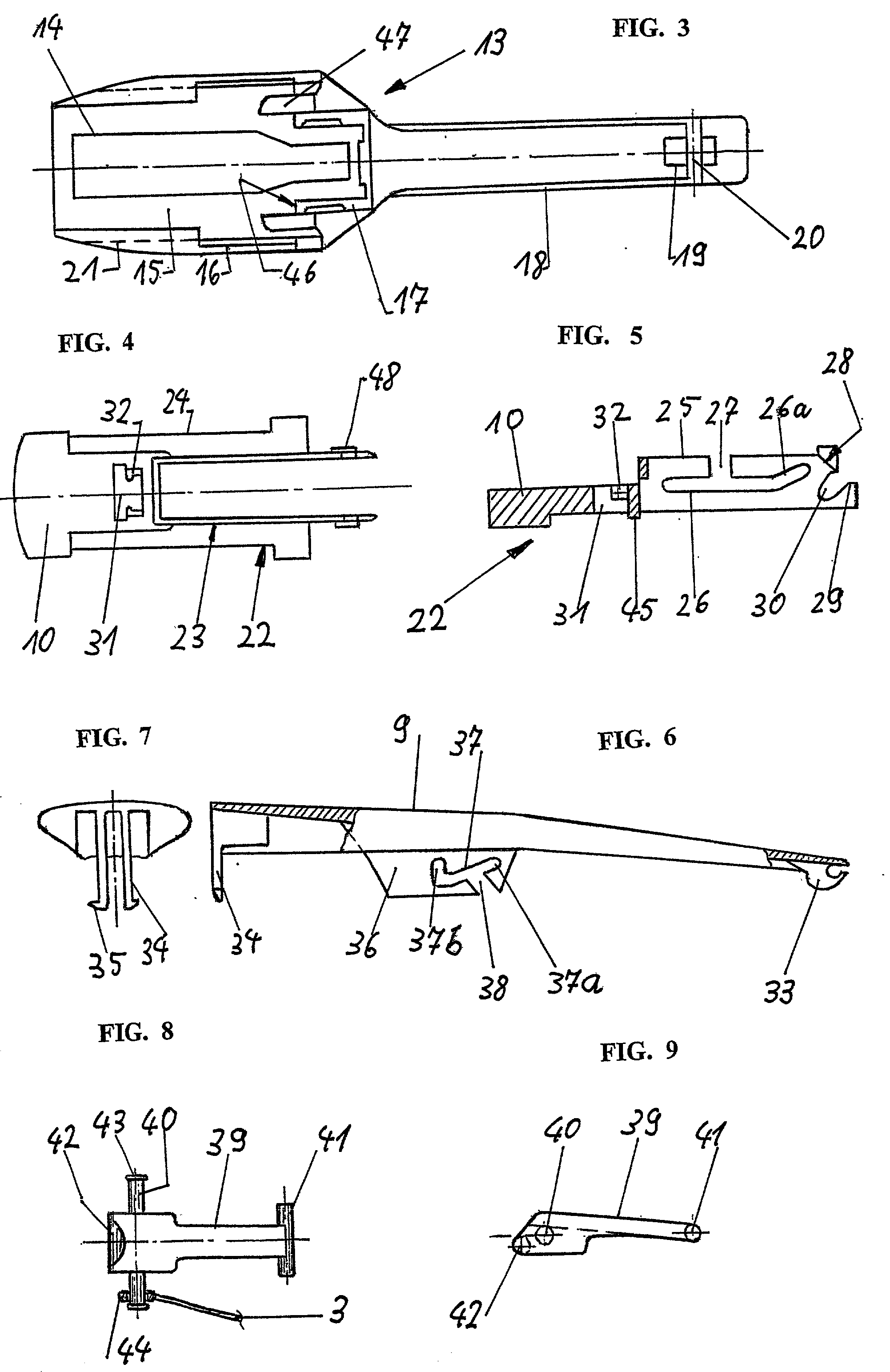
[0007] A further advantageous measure can consist of the slider comprising lateral walls comprising slots which form the longitudinal guide associated with the lower end region of the rocker; with lateral pins of the rocker leading through said slots, with a lace-up traction element being able to be attached to said pins. Accommodating the rocker on the movable slider, which slider is preferably provided in the housing comprising lateral walls, results in particularly good functional safety and facilitates inserting the device according to the invention in a shoe.
[0008] It is advantageous if the housing comprises a projecting tongue on which the tension lever is hingeably held by means of a snap-in claw. Arranging the tension lever on the housing makes it possible, in a simple way, to achieve good accuracy and functional safety while at the same time providing a unit which can be completely pre-assembled. The device according to the invention can thus be inserted in the associated shoe as a completely pre-assembled unit.

Problems solved by technology

This known arrangement is very expensive and not sufficiently reliable in its function.

Method used


Image

  • Device for activating a lace-up traction device for a shoe
  • Device for activating a lace-up traction device for a shoe
  • Device for activating a lace-up traction device for a shoe

Examples


Embodiment Construction

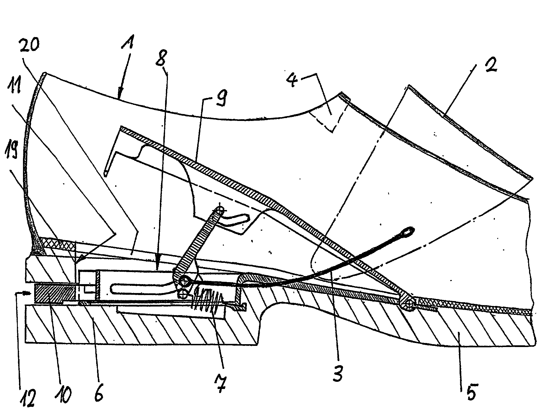
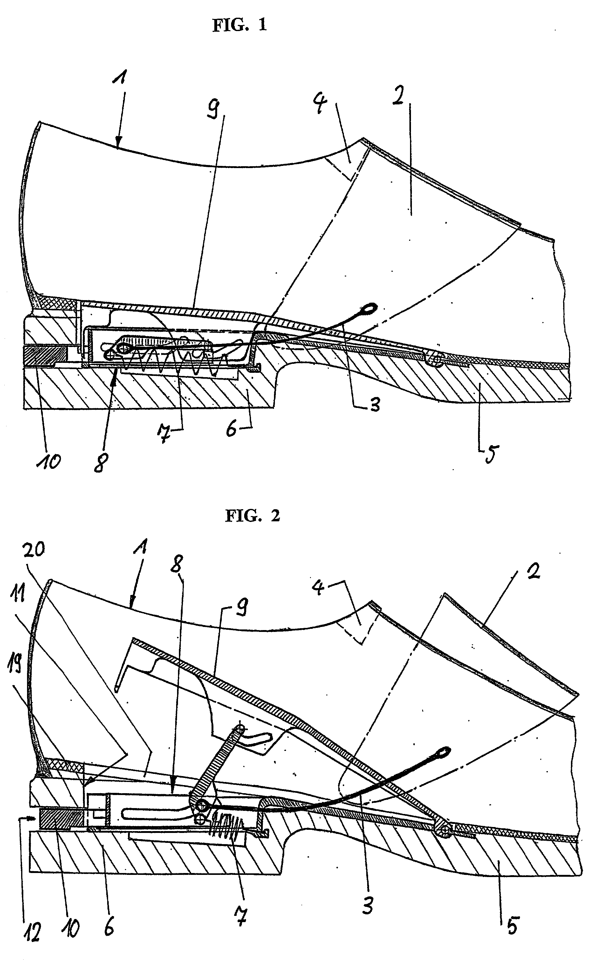
[0030] The shoe 1, which forms the basis of FIGS. 1 and 2, comprises a strap 2 encompassing the instep region which comprises an extension slit. A lace-up traction element 3 acts on each of the lateral ends of the strap 2. These can be plastic ribbons which are comparatively rigid under pressure, such plastic ribbons being able to act as push-and-pull elements. The lace-up traction elements 3 can comprise hooks which can be hooked into eyelets comprised in the strap. Advantageously, each side of the strap 2 comprises several eyelets. This makes it possible to adjust the desired tension of the entire lace-up traction device formed by the strap 2 and the lateral lace-up traction elements 3.

[0031] The lace-up traction elements 3 act on the underside of the strap 2, while on the shoe being arranged in a respectively associated channel. The lace-up traction elements 3 are therefore not visible from the outside. By moving the lace-up traction elements 3, the strap 2 can be moved from the ...


PUM


Abstract

In a device for activating a lace-up traction device for a shoe (1), comprising a slider (22) and a hingeably held tension lever (9) which can be pushed down when the shoe (1) is put on, said tension lever (9) in the pushed-down state being lockable to the slider (22) and being unlockable by pushing the slider (22) forward; said slider (22) comprising a guide (37) for a rocker (39), which rocker (39) elsewhere is guided in a further longitudinal guide (26) and which rocker (39) is pre-tensioned in the direction of hingeing forward and upward by means of a spring arrangement (7), a simple and clear design as well as good functional safety are achieved in that the guide (37) comprises two branches (37a, 37b) arranged at an angle in relation to each other; in that the slider (22) comprises a stopping face (28), and the rocker (39) comprises an associated engagement element (41) by means of which the slider (22) can be moved to the rear, into the rear snap-in position; and in that the slider (22) comprises a guide means (30), while the rocker (39) comprises an associated engagement element (41) by means of which the engagement element (41) of the rocker (39), which engagement element engages the guide (37), can be made to move to a position which is suitable for moving into the front branch (37a) of the guide (37).

Description

[0001] The invention relates to a device for activating a lace-up traction device for a shoe, comprising a housing arranged in the rear region of the substructure of the shoe, with a slider comprising a rearward projecting activation projecion being accommodated in said housing so as to be slidable in longitudinal direction of the shoe; said device further comprising a tension lever encompassing the housing, said tension lever being held at its front end so that he can hinge up or down and said lever being able to be pushed down by the heel of the foot when the shoe is put on; with said tension lever in its pushed down state being lockable with the slider which has been brought to a rearward snap-in position, and unlockable by moving the slider forward; and with the underside of said tension lever comprising a guide for the top end region of a rocker whose bottom end region acts together with lace-up traction elements and is guided in a longitudinal guide, which rocker being pretens...

Claims


Application Information

Patent Timeline
IPC IPC(8): A43B11/00A43C1/06A43B11/02A43B13/14A43B21/42A43B21/45A43C11/16
CPCA43B11/00Y10T24/37A43B21/45A43B21/42
Inventor VOSWINKEL, EGON
Owner VOSWINKEL EGON
Learn More