Bladder for use in a damping device

a technology for damping devices and blades, which is applied in the direction of shock absorbers, vibration dampers, springs/dampers, etc., can solve the problems of hydraulic fluid separation, oil, and limited use of twin tube shock absorbers to vehicles,

Inactive Publication Date: 2003-01-30
PROGRESSIVE SUSPENSION
View PDF0 Cites 22 Cited by
  • Summary
  • Abstract
  • Description
  • Claims
  • Application Information

AI Technical Summary

Problems solved by technology

However, as currently assembled, twin tube shock absorbers generally are not able to provide some of the high performance damping characteristics that are associated with monotube shock absorbers.
This has limited the use of twin tube shock absorbers to vehicles where performance handling is not considered to be important.
A common problem encountered with the use of shock absorbers is the separation of the hydraulic fluid, which is generally oil, from a compressible fluid, which is commonly a gas, such as air or nitrogen.
This mixing can lead to the entrapment of air bubbles in the hydraulic fluid, and the concomitant formation of foam as the shock absorber rebounds to an expanded condition.
Failure of the gas to rapidly separate from the hydraulic fluid can reduce the ability of a shock absorber to compress and rebound effectively, particularly if the shock absorber is forced to compress and rebound rapidly or repetitively, for instance, due to a series of closely spaced imperfections in the roadway.
Finally, these separation devices are prone to failure during general use of the shock absorber within which they are installed.

Method used


Image

  • Bladder for use in a damping device
  • Bladder for use in a damping device
  • Bladder for use in a damping device

Examples


Embodiment Construction

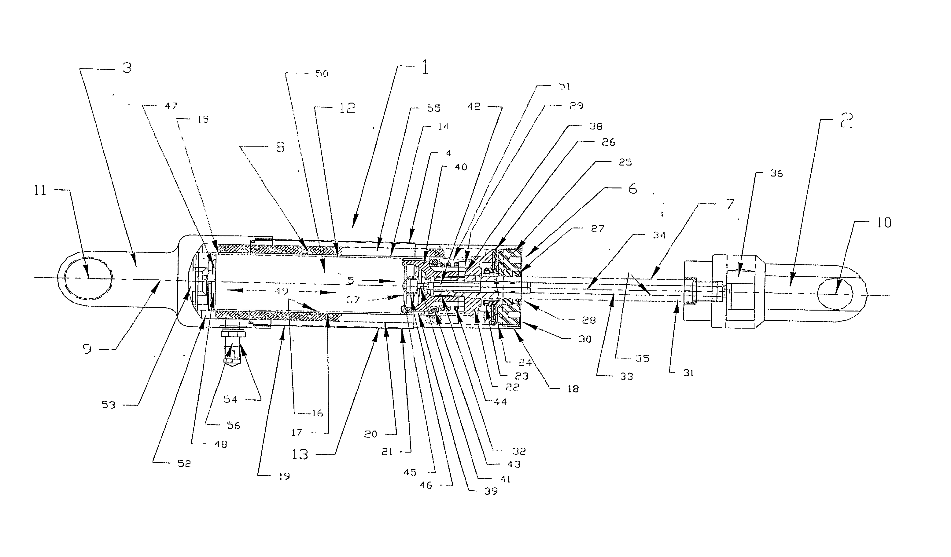
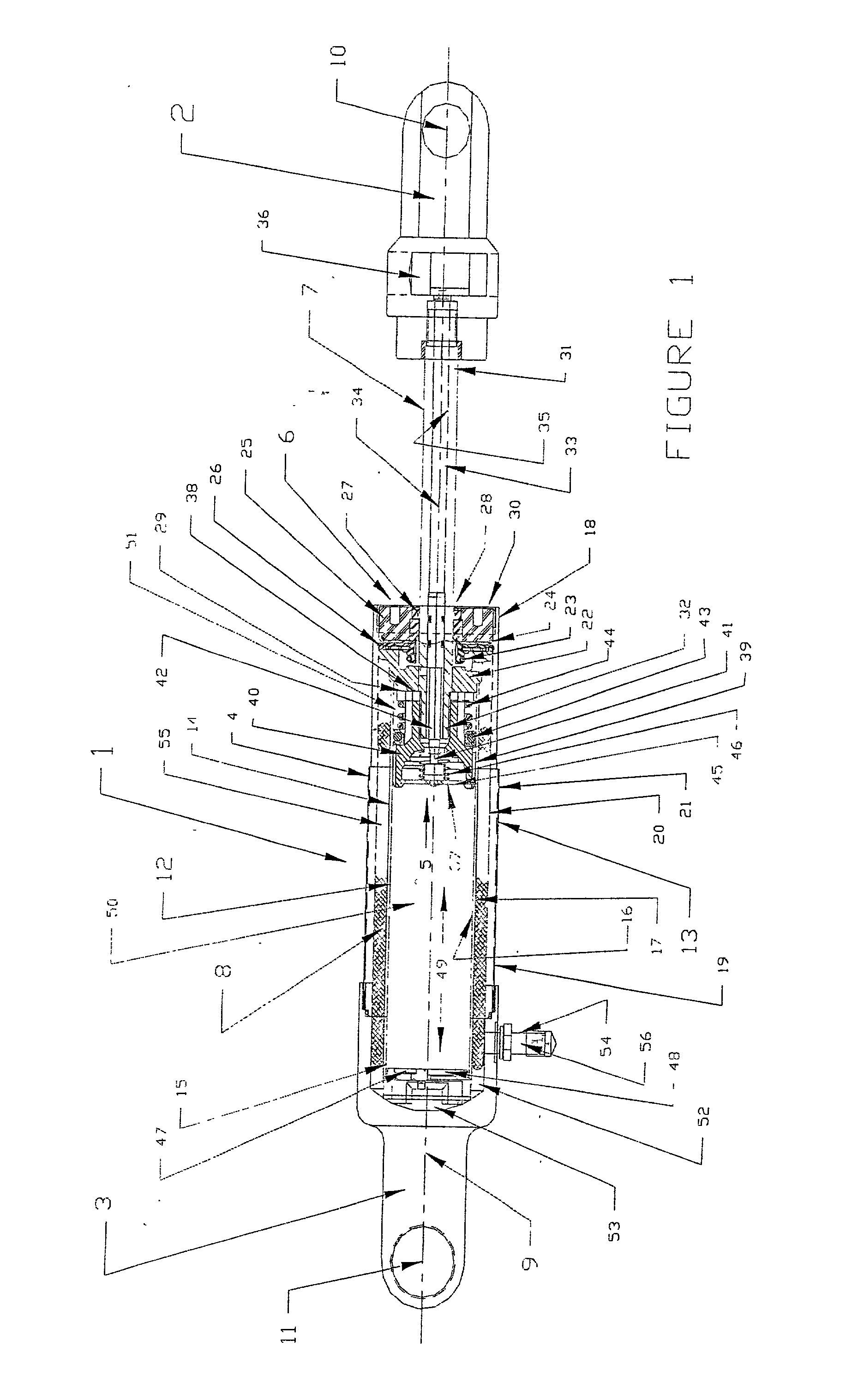
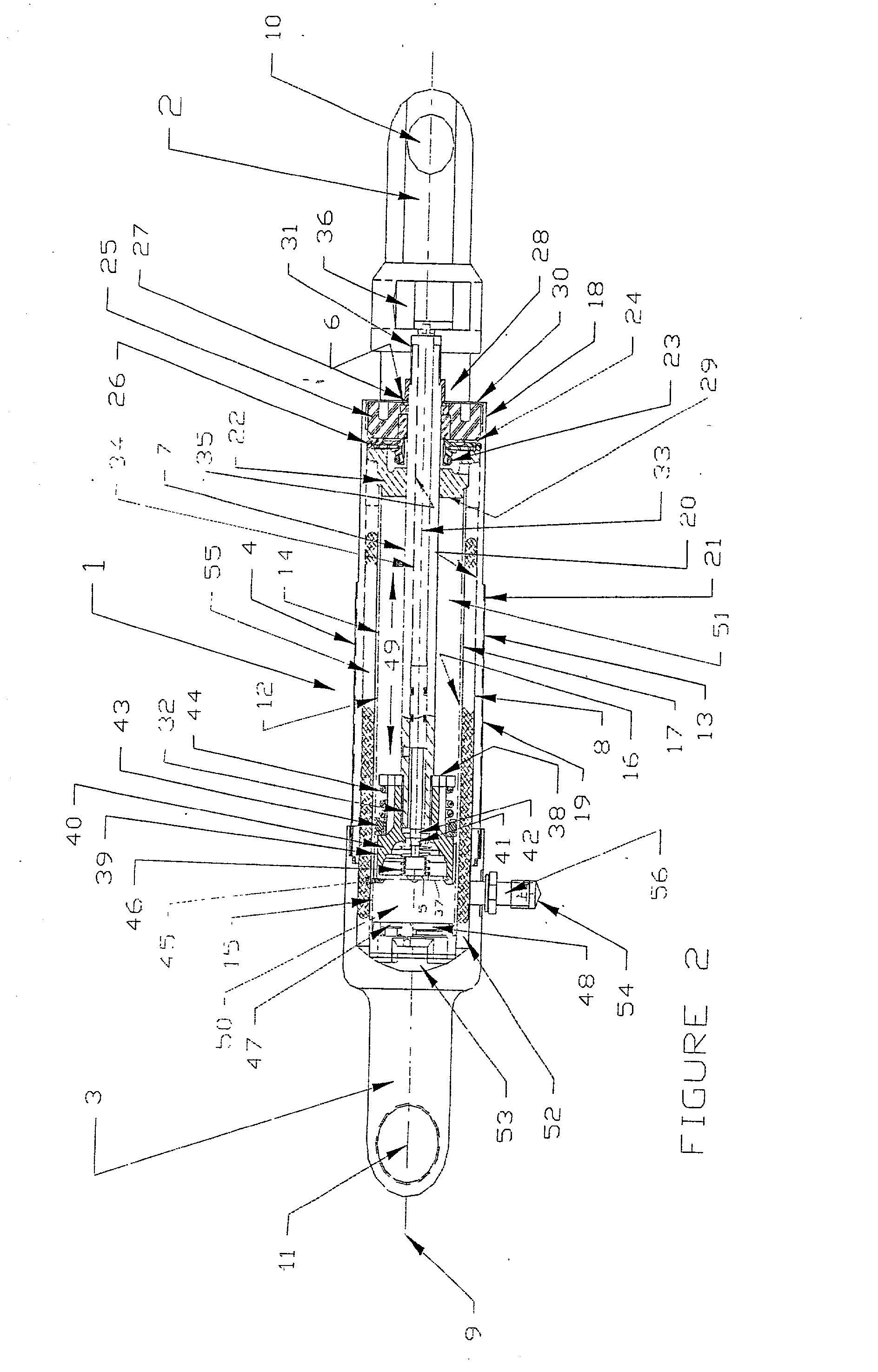
[0023] FIG. 1 and FIG. 2 illustrate an embodiment of a damping device in accordance with the present invention. In an embodiment,the damping device is a twin tube shock absorber 1, and comprises rod end mounts 2 and 3, a housing assembly 4, a piston assembly 5 and end cap assembly 6, a piston rod 7 and a bladder 8, located within the housing assembly 4. The piston assembly 5 is mounted within the housing assembly 4 for movement along the longitudinal axis 9. The piston assembly 5 is shown in FIG. 1 in an extended position and a retracted position in FIG. 2.

[0024] In an embodiment, rod end mount 2 and body end mount 3 are located on opposite ends of the shock absorber 1. Rod end mount 2 comprises an opening 10, within which is mounted a bushing, which is not shown in FIG. 1, that is comprised of durable, compressible material. The body end mount 3 is also comprised of an opening 11, within which is mounted a bushing comprised of a durable, compressible material.

[0025] In an embodimen...


PUM


Abstract

In an embodiment, the present invention provides a damping device that comprises a bladder that has an exterior surface and an interior surface, with the interior surface defining a chamber which stores a compressible fluid and a valve that is attached to the interior surface of the bladder. In an embodiment, the damping device contains a bladder that can be constructed from one or more of the following materials: urethane, neoprene, Viton, Nitrile, buna rubber, or silicon. The bladder is constructed to minimize the distance between the interior surface and the exterior surface. In an embodiment, the damping device contains a valve that can be constructed from one of the following materials: steel, brass, aluminum, or composite. The valve includes a stem that has threads for attaching a nut and a flange for attaching the valve to the interior surface of the bladder. The flange is contoured to maintain the axial location of the bladder within the damping device. In an embodiment, the flange is constructed from a material that is attachable to the interior surface of the bladder. In operation, compressible fluid is introduced into the bladder through the valve, with the valve permitting the adjustment of the internal pressure of a fluid contained within the bladder. The fluid volume within the bladder in an expanded condition as compared to the total displaceable volume of the piston rod is in a ratio of about 3:1. In an embodiment, the pressure within the bladder is at least 100 p.s.i, or at least 150 p.s.i.

Description

[0001] This application claims the benefit of U.S. Application Ser. No. 60 / 285,446 filed on Apr. 19, 2001, which is hereby fully incorporated by reference herein as though set forth in full.[0002] 1. Field of the Invention[0003] The present invention relates generally to bladders for use in damping devices.[0004] 2. Description of Related Art[0005] The following description includes information that may be useful in understanding the present invention. It is not an admission that any of the information provided herein is prior art, or relevant, to the presently claimed inventions, or that any publication specifically or implicitly referenced is prior art.[0006] A damping device is used to control the motions that are imparted to a vehicle as it is subjected to imperfections in the surface that the vehicle is traveling over. One type of damping device that is commonly used in vehicles is a shock absorber. There are two principal kinds of shock absorbers that are used in bicycles and ...

Claims


Application Information

Patent Timeline
Patent Type & Authority Applications(United States)
IPC IPC(8): F16F9/04F16F9/08F16F9/43
CPCF16F9/0472F16F9/08F16F9/435
Inventor HODGSON, SCOTT
Owner PROGRESSIVE SUSPENSION
Why Eureka
Try Eureka