Switchgear operating apparatuses

a technology for operating apparatuses and switchgears, applied in the direction of snap-action arrangements, high-tension/heavy-dress switches, switches, etc., can solve the problems of requiring a large amount of energy, and affecting the operation of switchgears, so as to prevent an intense shock

Inactive Publication Date: 2003-02-20
MITSUBISHI ELECTRIC CORP
View PDF0 Cites 9 Cited by
  • Summary
  • Abstract
  • Description
  • Claims
  • Application Information

AI Technical Summary

Benefits of technology

0049] In another aspect of the invention, the locking lever is rotatably mounted and maintains the energizing lever in its energized condition when locked by a rotatably mounted closing trigger, the energizing lever is unlocked when the locking lever locked by the closing trigger is released by turning the closing trigger by a swingable member swingably connected to a plunger of an electromagnet, and the energizing lever deactivator includes an operating member which causes the swingable member to swing when pushed by the cam and thereby prevents the closing trigger from turning even when the plunger moves.
0050] In this construction, the swingable member is caused to swing by pushing the operating member with the cam such that the closing trigger is not turned even if the plunger moves when the orientation of the cam is out of the specific angular range of rotation. This makes it possible to prevent an intense shock which could occur when the energizing lever released from the locking lever turns in its deenergizing direction and hits against the cam.

Problems solved by technology

Should this happen, it is likely that the circuit-breaking operation is interrupted halfway.
If the amount of this overrun is too large, a correspondingly large amount of energy is required.
Therefore, if the closing lever 37 is to be overrun with the aid of the inertia of the electric motor, it is necessary that the amount of overrun be sufficiently small so that the electric motor would not come to a halt halfway during its overrunning, and the individual components should be manufactured with high mechanical accuracy, resulting in an eventual cost increase.
Although it might be possible to employ an electric motor provided with a brake such that the second cam 50 can be stopped within the desired stopping range, this approach also results in a cost increase.
Furthermore, since the cam is braked by the braking device when the electric motor is in its final stage of inertial turning and its inertial energy has declined, energy required for braking is small and, therefore, the braking device may be of a simple structure.
Also, since the energy-storing device is already energized when the energizing lever is locked by the locking lever, the electric motor is kept from unnecessarily executing energizing operation.

Method used


Image

  • Switchgear operating apparatuses
  • Switchgear operating apparatuses
  • Switchgear operating apparatuses

Examples


first embodiment

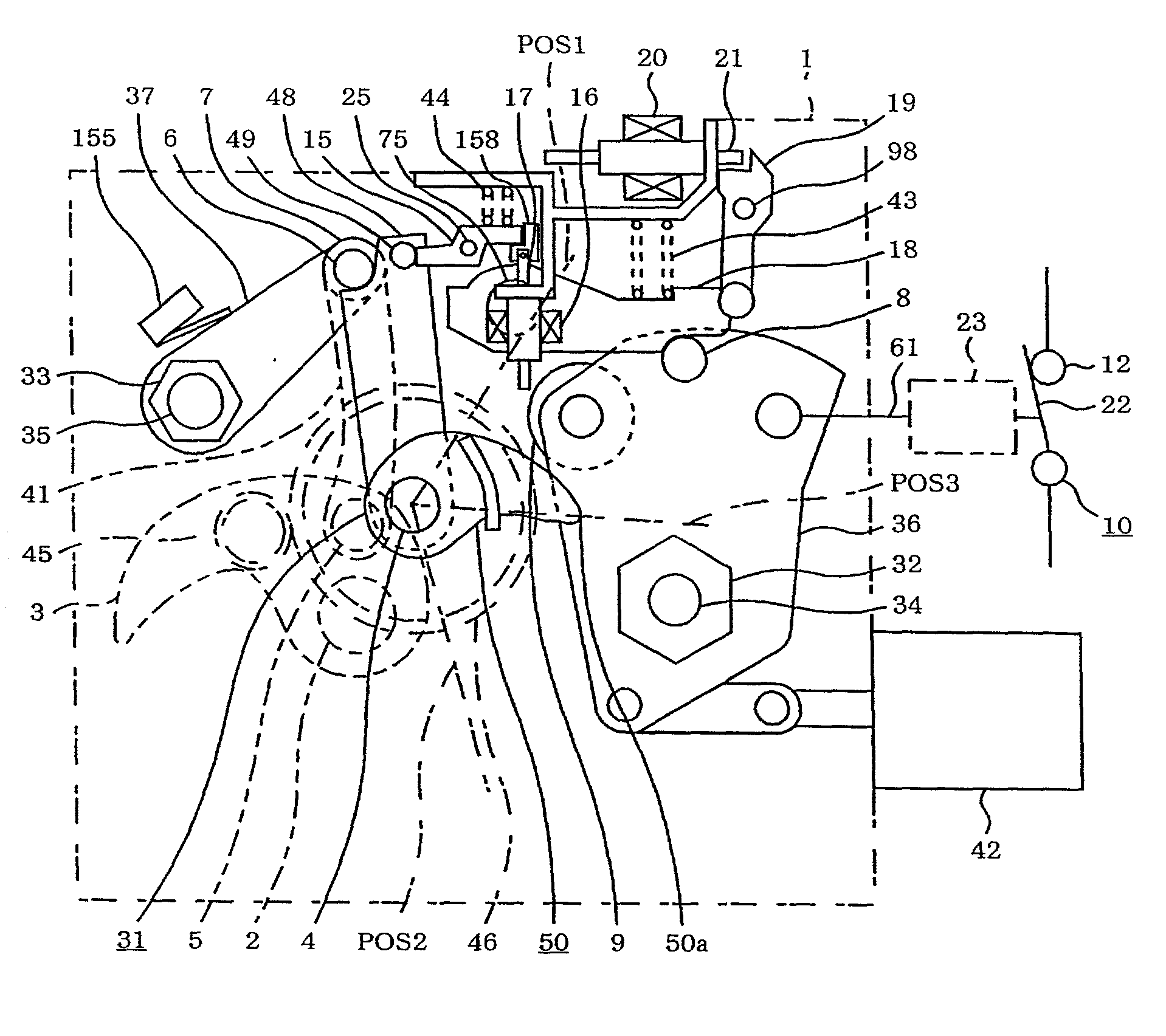
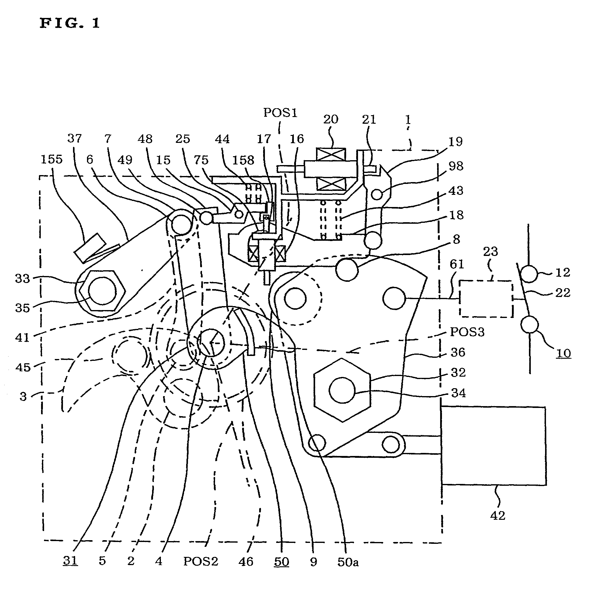
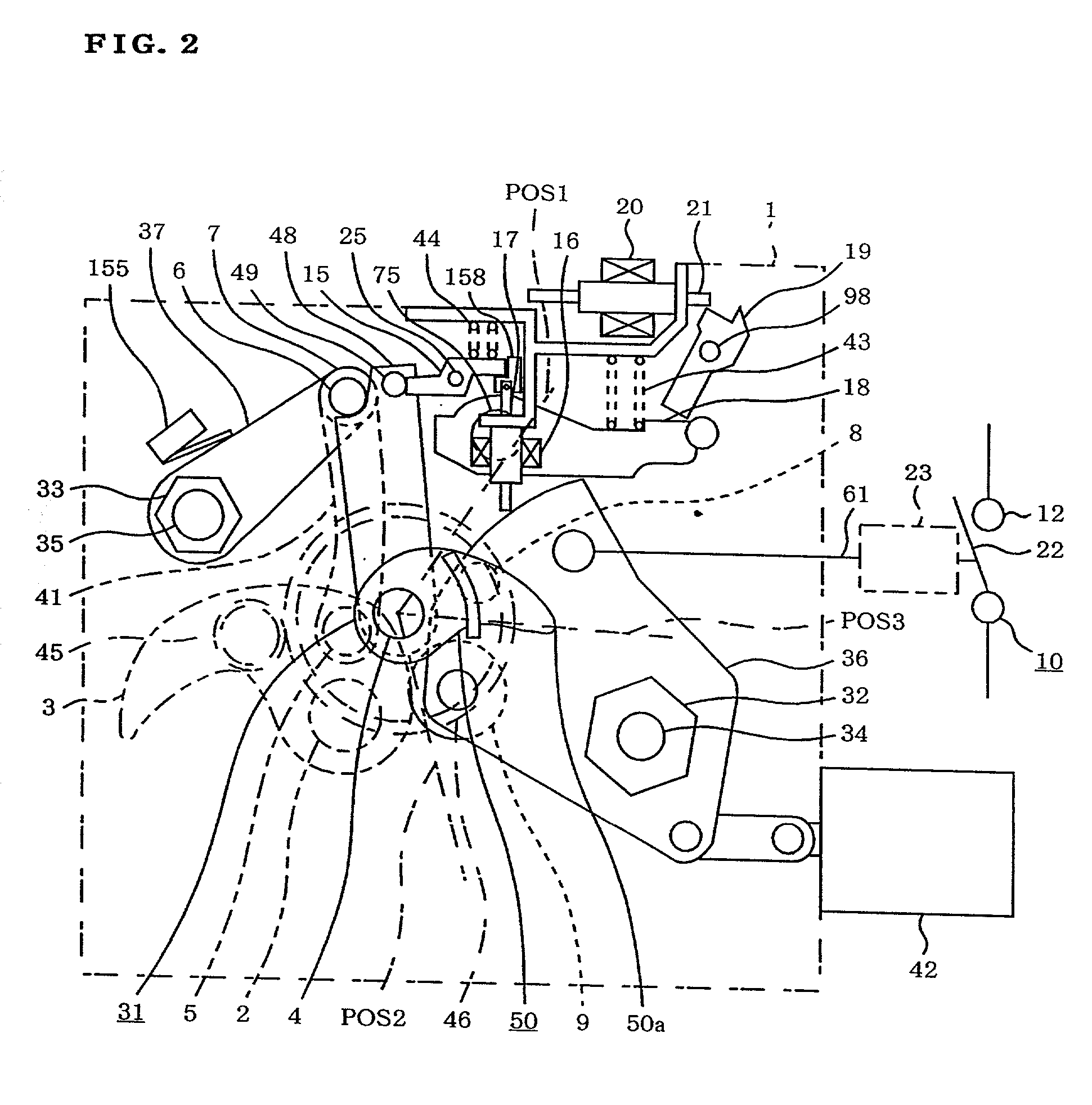
[0107] FIGS. 1-9 show an operating apparatus for a circuit breaker according to a first embodiment of the invention, in which FIG. 1 is a constructional diagram of the operating apparatus for the circuit breaker showing a state in which the circuit breaker is closed, torsion bars 29, 35, 28, 34 for making and breaking a circuit are all energized (caused to store elastic restoring energy by twisting), and a second cam 50 of an energizing mechanism 31 is stationary within a specific angular range .DELTA..theta. of rotation, and FIG. 2 is a constructional diagram of the operating apparatus for the circuit breaker of the first embodiment showing a state in which the circuit breaker is opened, the circuit-breaking torsion bars 28, 34 are deenergized (caused to release elastic restoring energy by restoring the original shape), the circuit-making torsion bars 29, 35 are energized, and the second cam 50 of the energizing mechanism 31 is stationary within the specific angular range .DELTA..t...

second embodiment

[0143] FIGS. 10-19 show an operating apparatus for a circuit breaker according to a second embodiment of the invention, in which FIG. 10 is a perspective view of the operating apparatus for the circuit breaker. FIG. 11 is a constructional diagram of the operating apparatus for the circuit breaker of the second embodiment showing a state in which the circuit breaker is closed, a circuit-breaking coil spring 60 and a circuit-making coil spring 77 are both energized, and a second cam 50 of an energizing mechanism 31 is stationary within a specific angular range .DELTA..theta. of rotation. FIG. 12 is a constructional diagram of the operating apparatus for the circuit breaker of the second embodiment showing a state in which the circuit breaker is opened, the circuit-breaking coil spring 60 is deenergized, the circuit-making coil spring 77 is energized, and the second cam 50 of the energizing mechanism 31 is stationary within the specific angular range .DELTA..theta. of rotation.

[0144] F...

third embodiment

[0161] FIGS. 20-28 show an operating apparatus for a circuit breaker according to a third embodiment of the invention, in which FIG. 20 is a constructional diagram of the operating apparatus for the circuit breaker of the third embodiment showing a state in which the circuit breaker is closed, a circuit-breaking coil spring 60 and a circuit-making coil spring 77 are both energized. FIG. 21 is a constructional diagram of the operating apparatus for the circuit breaker of the third embodiment showing a state in which a circuit-breaking operation is being executed from the state shown in FIG. 20. FIG. 22 is a constructional diagram of the operating apparatus for the circuit breaker of the third embodiment showing a state in which the circuit-making coil spring 77 is energized and the circuit-breaking coil spring 60 is deenergized upon completion of the circuit-breaking operation from the state shown in FIG. 21.

[0162] FIG. 23 is a constructional diagram of the operating apparatus for th...


PUM


Abstract

The invention provides a compact, lightweight and low-cost operating apparatus for a switchgear. A second cam (50) turned counterclockwise by an electric motor begins to maintain contact with a closing lever (37) at a first angular position (POS1), turns the closing lever (37) counterclockwise to energize a circuit-making coil spring (77), and causes a closing latch (48) to lock the closing lever (37). The second cam (50) further turning counterclockwise becomes separated from the closing lever (37) and actuates a cam switch (156) at a second angular position (POS2) to interrupt an electric current supplied to the electric motor. The second cam (50) further turns due to inertial turning of the electric motor and is braked by a elastic brake member (159) at a third angular position (POS3), whereby the second cam (50) stops within a specific angular range DELTAtheta of rotation. Despite its simple structure, the elastic brake member (159) can halt the second cam (50) in a reliable fashion.

Description

BACKGROUND OF THE INVENTION AND RELATED ART STATEMENT[0001] The present invention relates to an improvement of operating apparatuses for switchgears like circuit breakers used as electric power switching devices installed in an electric power substation or in a switching station, for example.[0002] A conventionally available operating apparatus for a circuit breaker, which is a typical example of switchgears, utilizes an elastic force exerted by a spring as an operating force. FIGS. 32-35 show a conventional operating apparatus for a circuit breaker disclosed in Japanese Laid-open Patent Publication No. 63-304542, in which FIG. 32 is a perspective view generally showing the construction of the operating apparatus for the circuit breaker, and FIG. 33 is a constructional diagram of the operating apparatus for the circuit breaker of FIG. 32 showing a state in which the circuit breaker is closed and torsion bars 29, 35, 28, 34 for making and breaking a circuit are all energized (caused ...

Claims


Application Information

Patent Timeline
Patent Type & Authority Applications(United States)
IPC IPC(8): H01H3/30H01H33/40H01H3/62H01H33/42
CPCH01H3/3015H01H3/3042H01H3/62
Inventor MORI, TOMOHITOOHTSUKA, KYOICHINAKAJIMA, NOBUYA
Owner MITSUBISHI ELECTRIC CORP
Why Eureka
Try Eureka