Hydraulic vibration-damping support

a technology of vibration-damping support and hydraulic technology, which is applied in the direction of machine supports, shock absorbers, jet propulsion mountings, etc., can solve the problems of increasing the cost and weight of the vibration-damping support, and achieve the effect of reducing the drawbacks

Inactive Publication Date: 2003-02-27
HUTCHINSON SA
View PDF8 Cites 17 Cited by
  • Summary
  • Abstract
  • Description
  • Claims
  • Application Information

AI Technical Summary

Benefits of technology

0013] A particular object of the present

Problems solved by technology

Unfortunately, the above-mentioned vibration-damping support suffers from the drawback that the casting of its rigid partition is relati

Method used


Image

  • Hydraulic vibration-damping support
  • Hydraulic vibration-damping support
  • Hydraulic vibration-damping support

Examples


Embodiment Construction

[0036] In the various figures, like references designate identical or similar elements.

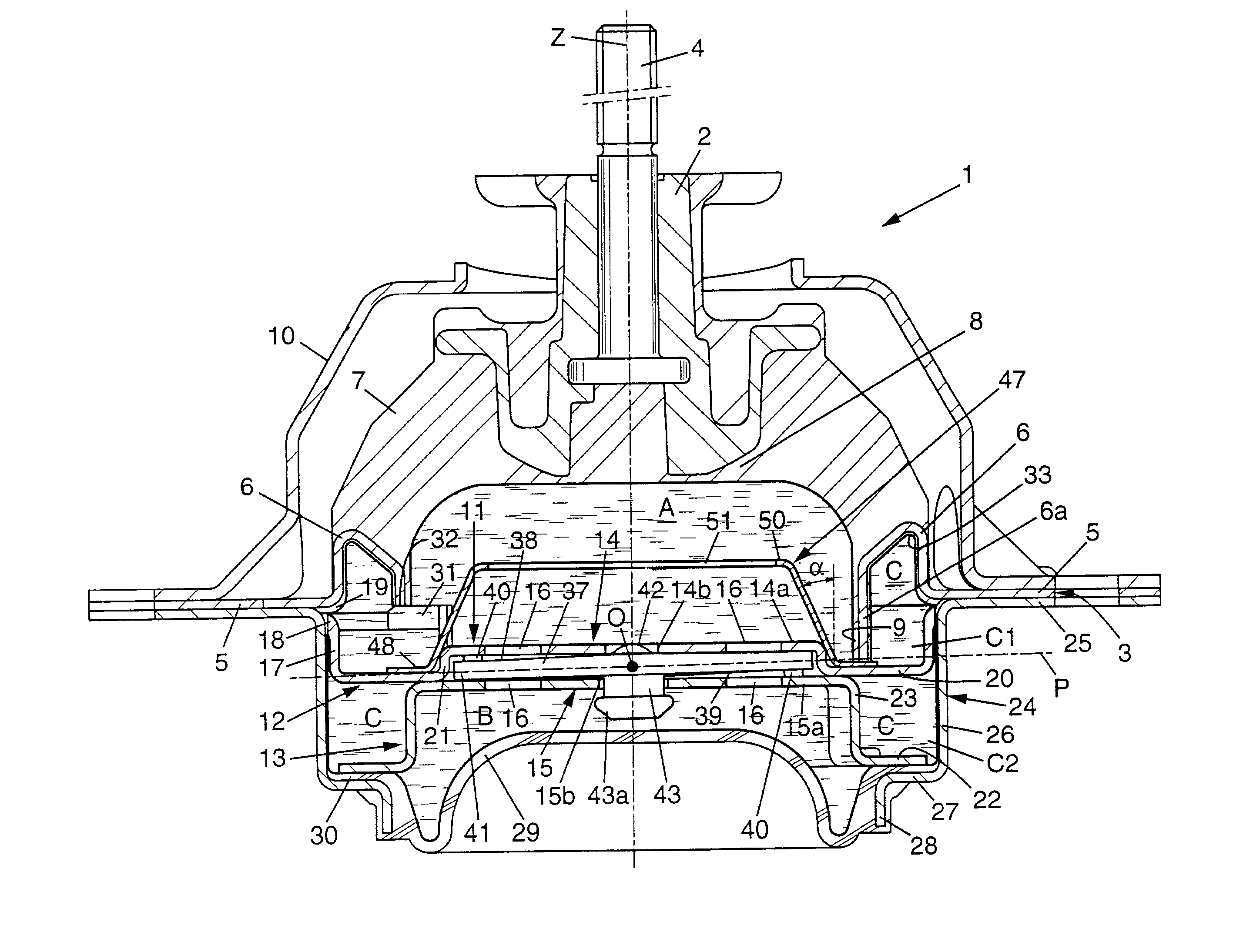
[0037] FIG. 1 shows a hydraulic vibration-damping support 1 having first and second strength members 2, 3 which, for example, serve to be fixed respectively to the engine-and-gearbox unit and to the body of a vehicle.

[0038] In the example in question, the first strength member 2 is in the form of a metal block made of a light alloy, for example. The metal block is centered on a vertical axis Z and it is secured to a threaded pin 4 making it possible, for example, to fix the block to the engine-and-gearbox unit.

[0039] The second strength member 3 is formed by a ring of cut-out and stamped sheet metal, also centered on the axis Z. In the example shown, the second strength member 3 has an outer portion 5 that extends in a radial plane about the axis Z and that serves, for example, to be fixed to the body of the vehicle, and an inner portion 6 that is recessed, that is of substantially upside-down U s...


PUM


Abstract

A hydraulic vibration-damping support comprising two strength members interconnected by an elastomer body defining in part a working chamber filled with liquid, said working chamber communicating via a constricted passage with a compensation chamber separated from said working chamber by a rigid partition. The constricted passage is made up of two stages defined by two pieces of sheet metal forming the rigid partition.

Description

[0001] The present invention relates to hydraulic vibration-damping supports serving, for example, for mounting motor vehicle engines on the bodies of such vehicles.[0002] More precisely, the invention relates to a hydraulic vibration-damping support serving to interconnect first and second rigid elements so as to damp and filter vibration between said elements, the support comprising:[0003] first and second rigid strength members serving to be fixed to respective ones of the first and second rigid elements to be interconnected;[0004] an elastomer body that is substantially bell-shaped, extending about a central axis between a top secured to the first strength member and an annular base secured to the second strength member;[0005] a working chamber filled with liquid and defined at least in part by the elastomer body;[0006] a compensation chamber filled with liquid and defined at least in part by a flexible elastomer wall;[0007] a rigid partition that separates the working chamber f...

Claims


Application Information

Patent Timeline
IPC IPC(8): F16F13/10B60K5/12F16F13/18
CPCF16F13/103F16F13/105F16F2226/00
Inventor PIZANTI, THIERRYCOLLET, LOIC
Owner HUTCHINSON SA
Why Eureka
Try Eureka