Heart valve prosthesis and sutureless implantation of a heart valve prosthesis

a heart valve and prosthesis technology, applied in the direction of prosthesis, instruments, blood vessels, etc., can solve the problems of too much risk in placing an individual on cardiopulmonary bypass, too ill patients with deficient aortic or pulmonary valves to survive conventional open-heart surgery, etc., and achieve the effect of reducing the cross-sectional dimension

Inactive Publication Date: 2003-02-27
EDWARDS LIFESCI CARDIAQ
View PDF2 Cites 944 Cited by
  • Summary
  • Abstract
  • Description
  • Claims
  • Application Information

AI Technical Summary

Benefits of technology

[0008] One aspect of the present invention provides a method for implanting a heart valve prosthesis. The heart valve prosthesis is inserted into a generally cylindrical and elongated enclosure, such that the prosthesis has a reduced cross-sectional dimension generally corresponding to an internal dimension of the cylindrical enclosure. The prosthesis is of the type that is operative to expand to a desired size and configuration when discharged from the enclosure. An opening is formed in tissue and the portion of the enclosure holding the prosthesis is inserted through the opening. The location of the opening can provide a substantially direct path to a desired implantation site for the prosthesis. After the cylindrical enclosure is positioned at a desired position, the prosthesis is discharged from the enclosure. As a result, the discharged heart valve prosthesis expands from the reduced cross-sectional dimension to an expanded cross-sectional dimension, such that an exterior portion of the heart valve prosthesis engages adjacent tissue to mitigate axial movement of the prosthesis relative to the adjacent tissue. The method can be performed without cardiopulmonary bypass as well as can be performed without opening the patient's heart.

Problems solved by technology

In certain situations, an individual requiring a heart valve replacement may be sufficiently ill, such that placing the individual on cardiopulmonary bypass may pose too great of risk.
In particular, many older patients having a deficient aortic or pulmonic valve may be too ill to survive conventional open-heart surgery.

Method used


Image

  • Heart valve prosthesis and sutureless implantation of a heart valve prosthesis
  • Heart valve prosthesis and sutureless implantation of a heart valve prosthesis
  • Heart valve prosthesis and sutureless implantation of a heart valve prosthesis

Examples


Embodiment Construction

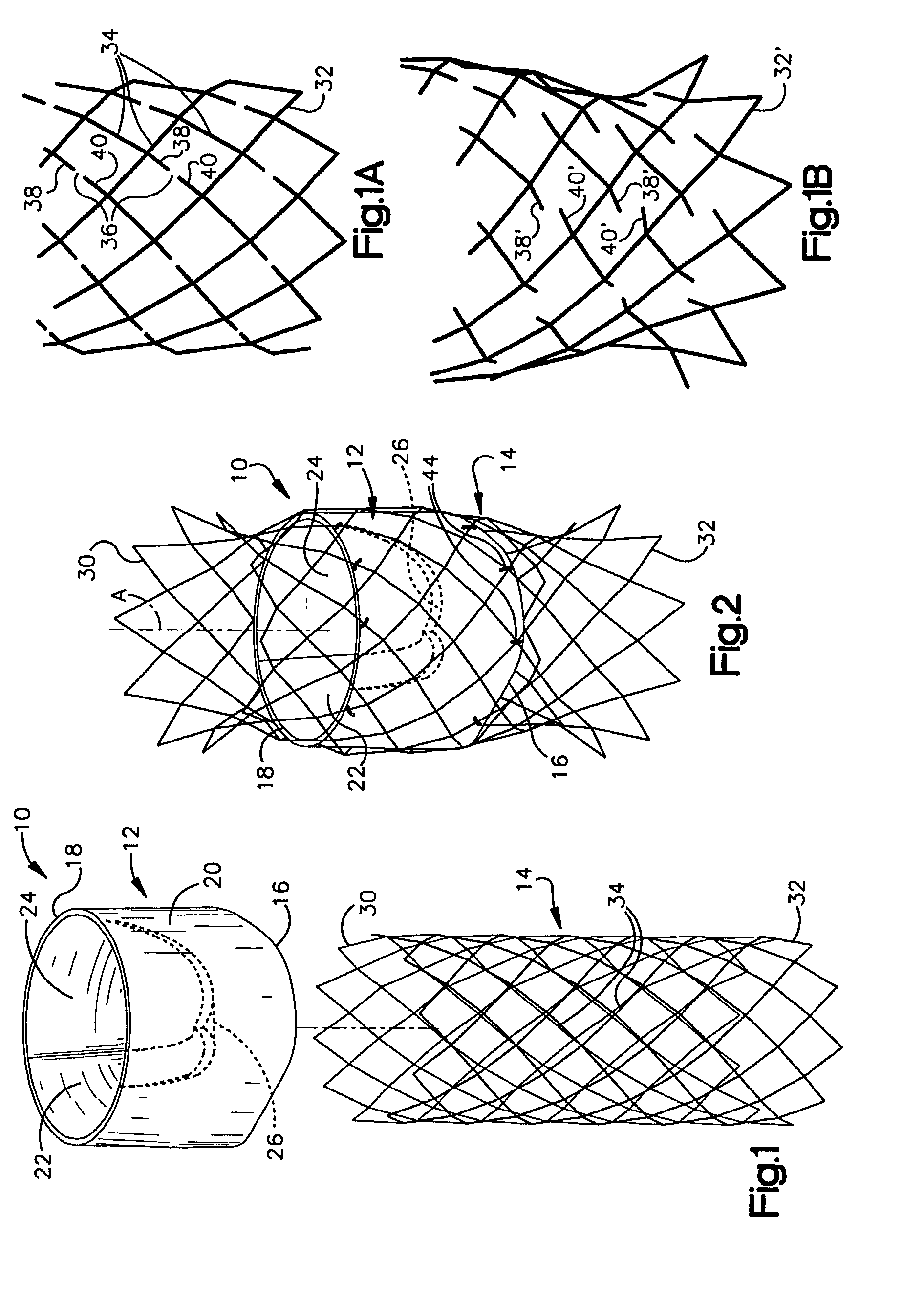
[0041] FIG. 1 is an exploded view of a valvular prosthesis 10 in accordance with an aspect of the present invention. The prosthesis 10 includes a valve portion 12 and a stent portion 14 that may be assembled to form the valvular prosthesis 10, such as shown in FIG. 2.

[0042] The valve portion 12 includes inflow and outflow ends 16 and 18 spaced apart from each other by a length of a generally cylindrical sidewall portion 20. While the inflow and outflow ends 16 and 18 are illustrated as being annular in FIGS. 1 and 2, those skilled in the art will understand and appreciate that other configurations (e.g., generally sinusoidal ends) also could be used in accordance with the present invention.

[0043] The valve portion 12 also includes one or more leaflets 22, 24, and 26 that are attached to and extend from an interior of the sidewall portion 20. In the example illustrated in FIGS. 1 and 2, the valve portion 12 includes three leaflets 22, 24 and 26, although other numbers of leaflets, su...


PUM


Abstract

A method of implanting a heart valve prosthesis is disclosed. A valve is mounted within a support apparatus that is deformable between an expanded and a reduced cross-sectional condition. The prosthesis can be implanted into a patient's heart, such as during a direct vision procedure through a generally tubular implantation apparatus that maintains the prosthesis in its reduced cross-sectional condition until discharged from the tubular apparatus at a desired implantation site.

Description

REFERENCE TO RELATED APPLICATION[0001] This application is a continuation-in-part of U.S. patent application Ser. No. 09 / 973,609, which was filed on Oct. 9, 2001, and entitled HEART VALVE PROSTHESIS AND SUTURELESS IMPLANTATION OF A HEART VALVE PROSTHESIS, which is a continuation-in-part of U.S. patent application Ser. No. 09 / 659,882, which was filed on Sep. 12, 2000 and entitled VALVULAR PROSTHESIS AND METHOD OF USING SAME, which is incorporated herein by reference.[0002] The present invention relates to an implantable prosthetic device and, more particularly, to a heart valve prosthesis and to a method of implanting the prosthesis.[0003] It is well known to utilize mechanical heart valves, such as the ball check valve, and natural tissue cardiac valves to replace defective aortic and mitral valves in human patients. One type of natural tissue heart valve typically employs a porcine valve for implantation in a human, as they are very similar to human valves of appropriate size and g...

Claims


Application Information

Patent Timeline
Patent Type & Authority Applications(United States)
IPC IPC(8): A61F2/06A61F2/24A61F2/82A61F2/84
CPCA61F2/2418A61F2/2436A61F2/2475G01N2800/52Y10S623/904A61F2230/005A61F2230/0054A61F2230/0067A61F2230/0078A61F2220/0016A61F2210/0014A61F2/2427A61F2/2409A61F2/2433
Inventor GABBAY, SHLOMO
Owner EDWARDS LIFESCI CARDIAQ
Why Eureka
Try Eureka