Implantable medical lead

a medical lead and implantable technology, applied in the field of implantable medical leads, can solve the problems of difficult separation of the contribution of the motion artifact from the useful signal contribution from pressure changes, the cross-section dimension of the cardiac lead is decreased, and the resistance of the lead is increased

Active Publication Date: 2016-03-29
ST JUDE MEDICAL
View PDF11 Cites 0 Cited by
  • Summary
  • Abstract
  • Description
  • Claims
  • Application Information

AI Technical Summary

Benefits of technology

[0010]The above object is achieved in accordance with the present invention by an implantable lead for sensing mechanical activity of a human heart having a first non-conductive polymeric tube extending from a proximal end to a distal end of the lead, a first conductor provided in a lumen of the first polymeric tube, and a sensor connected to the first conductor at a distal end thereof. Furthermore, the first polymeric tube is provided with a conductive inner surface layer, so as to prevent accumulation of electrical charges between said first conductor and said first polymeric tube.
[0011]Thus, the present invention is based on the advantageous idea of providing the cardiac lead connecting an intracardiac sensor to an implantable medical device, such as a cardiac stimulator, with electrically insulating tubing having an electrically conductive surface layer facing and contacting the conductor. By configuring the cardiac lead in such a manner, it has surprisingly been found that the contribution of motion artifacts to the sensor signal is greatly reduced. Thus, the effect of the motion artifacts is reduced to such an extent, that the contribution thereof to the sensor signal can be easily separated from the contribution of the characteristics, e.g. pressure changes, which the sensor is arranged to detect and measure.
[0014]By providing the surface of the tubing facing and contacting the conductor, in the one conductor system, or the conductors, in the two conductor system with an electrically conducting layer, there will be essentially no accumulation of electrical charges along the conductors. It has surprisingly been found that the contribution of motion artifacts to the sensor signal is greatly reduced and virtually eliminated, as described above.
[0026]According to further embodiments of the present invention, the conductive surface layer of the polymeric tubing is further arranged to have a lubricating effect. Due to the continued efforts in decreasing the cross-section dimensions of cardiac leads, along with development of new materials for the polymeric tubing with increased adhering properties, cardiac leads become increasingly difficult to assemble. By providing the conductive surface layer of the polymeric tubing with lubricating properties, the frictional force between the polymeric tubing and the conductors could be significantly reduced.
[0027]Thereby, not only would the conductive surface layer reduce or eliminate the effects of motion artifacts on the sensor signal, the lubricating effect of the layer would also facilitate the assembly of the cardiac lead. According to one preferred embodiment, the surface layer of the tubing comprises graphite, which has both lubricating and conductive properties. However, other suitable materials having both lubricating and conducting properties could be used without departing from the scope of the present invention, in particular the carbonaceous materials mentioned herein.

Problems solved by technology

However, when using a piezoelectric sensor, such as a pressure sensor or an accelerometer, within a chamber of the heart or a blood vessel, measurements have shown that the voltage signal produced by the sensor is affected by motion artifacts.
The motion artifacts could be large enough to disturb a sensor signal, especially when using a piezoelectric pressure sensor since the voltage changes produced by the piezoelectric sensor from pressure changes are very small.
Furthermore, it could be difficult to separate the contribution of the motion artifacts from the useful signal contribution from pressure changes.
Thus, depending on the contribution from the motion artifacts and the magnitude of the useful contribution to the pressure signal, the interpretation of the sensor signal could be rendered difficult or even impossible.

Method used


Image

  • Implantable medical lead
  • Implantable medical lead
  • Implantable medical lead

Examples


Embodiment Construction

[0034]The following is a description of preferred embodiments in accordance with the present invention. This description is intended for describing the general principles of the invention and is not to be taken in a limiting sense. Thus, even though a biventricular heart stimulator for sensing and stimulating in both ventricles is being illustrated, the invention is also applicable to heart stimulators arranged for sensing and stimulating in one ventricle only, and / or for stimulating in the atria of a human heart. Furthermore, the invention is also applicable to implantable cardioverter-defibrillators (ICD).

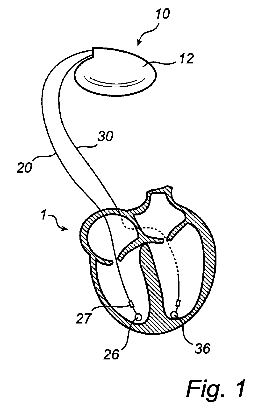
[0035]Referring first to FIG. 1, there is shown an implantable heart stimulator 10 in electrical communication with a human heart 1 via two cardiac leads 20, 30 arranged for stimulation and sensing. Moreover, the heart stimulator 10 comprises electronic circuitry and a battery contained within a hermetically sealed pacemaker housing 12. The housing 12 has a metallic casing of tit...


PUM


Abstract

An implantable lead for sensing mechanical activity of a human heart has an insulating polymeric tube extending from a proximal end to a distal end of the lead, an electrical conductor provided in the lumen of the polymeric tube, and a sensor connected to the conductor at the distal end thereof. The polymeric tube is provided with a conductive surface layer along the inner face between the polymeric tube and the electrical conductor, the conductive surface layer being in electrical contact with this conductor. Accumulation of electrical charges between the electric conductor and the polymeric tube is thereby prevented.

Description

BACKGROUND OF THE INVENTION[0001]1. Field of the Invention[0002]The present invention generally relates to the field of implantable medical devices. More specifically, the present invention relates to an implantable lead for sensing mechanical activity of a human heart, the lead comprising a first non-conductive polymeric tube extending from a proximal end to a distal end of said lead, a first conductor provided in a lumen of said first polymeric tube, and a sensor.[0003]2. Description of the Prior Art[0004]Within the field of implantable medical devices, such as cardiac stimulators, cardioverters and defibrillators, different types of sensors have long been used for sensing and monitoring mechanical and electrical characteristics of the human heart. For instance, piezo-resistive, piezocapacitive or piezoelectric sensors could be used for sensing mechanical properties, such as pressure changes in the heart or in other blood vessels.[0005]One example of a piezoelectric sensor suitabl...

Claims


Application Information

Patent Timeline
Patent Type & Authority Patents(United States)
IPC IPC(8): A61N1/05A61N1/365
CPCA61N1/056A61N1/36564
Inventor NILSSON, KENTHJOHANSSON, ANNA-KARINERIKSSON, TOM
Owner ST JUDE MEDICAL
Why Eureka
Try Eureka