Composite encapsulated engine mount

a technology of engine mounts and encapsulated parts, which is applied in the direction of machine supports, jet propulsion mountings, other domestic objects, etc., can solve the problems of high tooling cost and additional assembly steps of these arrangements, and achieve the effects of reducing weight, reducing the cost of forming rubber bushings, and increasing spa

Inactive Publication Date: 2011-12-01
COOPER STANDARD AUTOMATIVE INC
View PDF0 Cites 1 Cited by
  • Summary
  • Abstract
  • Description
  • Claims
  • Application Information

AI Technical Summary

Benefits of technology

[0010]Curing of the moldable material reduces a cross-sectional dimension of the bushing upon shrinking, and thereby retains the bushing in the bracket.
[0014]A primary advantage associated with the method of assembly and the resultant mount assembly is the reduced weight resulting from use of a composite or plastic bracket instead of a metal bracket.
[0015]Another advantage resides in the reduced cost of forming the rubber bushing because the bushing can be molded in a large number, multi-cavity mold rather than injecting rubber into cast or molded composite brackets that take up more room in the same size molding machine.
[0017]Reduced heating is also associated with the new process since elevated temperatures are no longer required to assure cross-linking of the rubber bushing.
[0018]Another advantage resides in the elimination of secondary operations of swaging or pressing a bushing into a bracket opening.

Problems solved by technology

Further, additional assembly steps and high tooling costs are associated with these arrangements.

Method used


Image

  • Composite encapsulated engine mount
  • Composite encapsulated engine mount
  • Composite encapsulated engine mount

Examples


Embodiment Construction

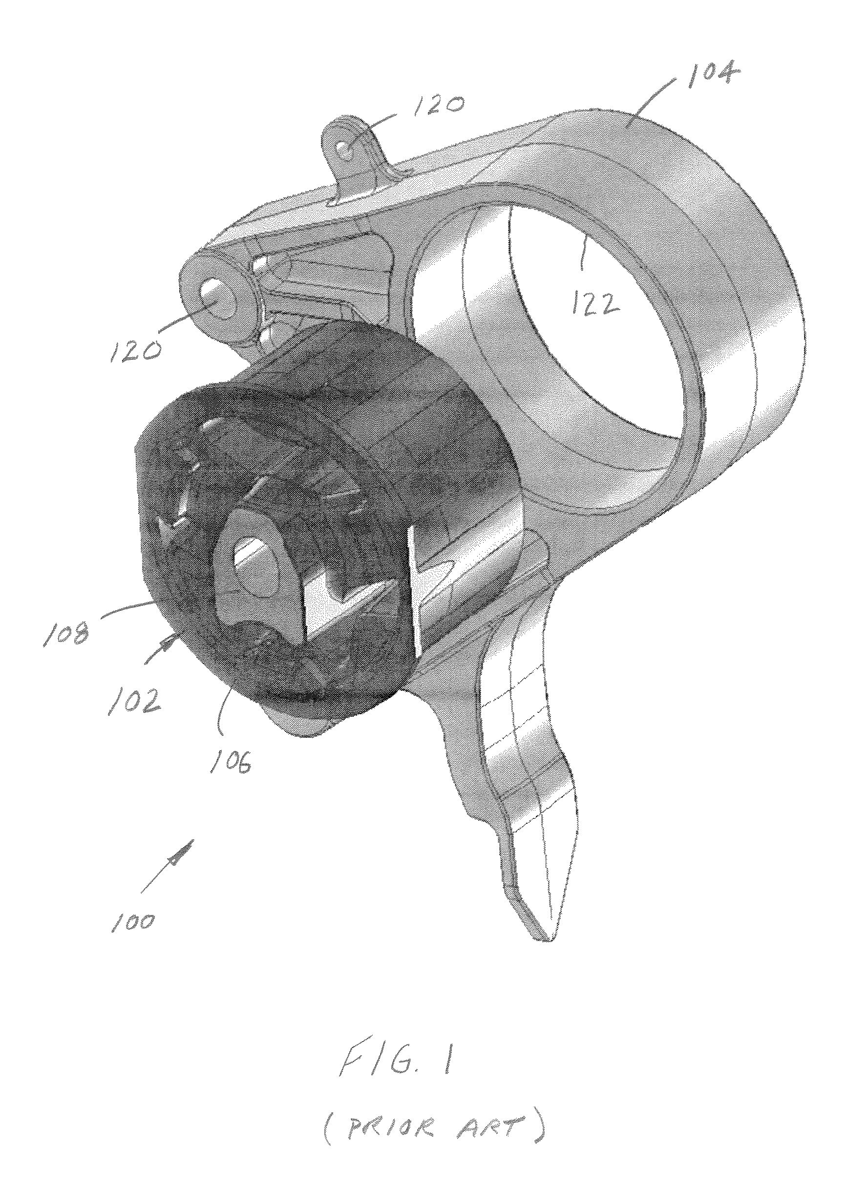
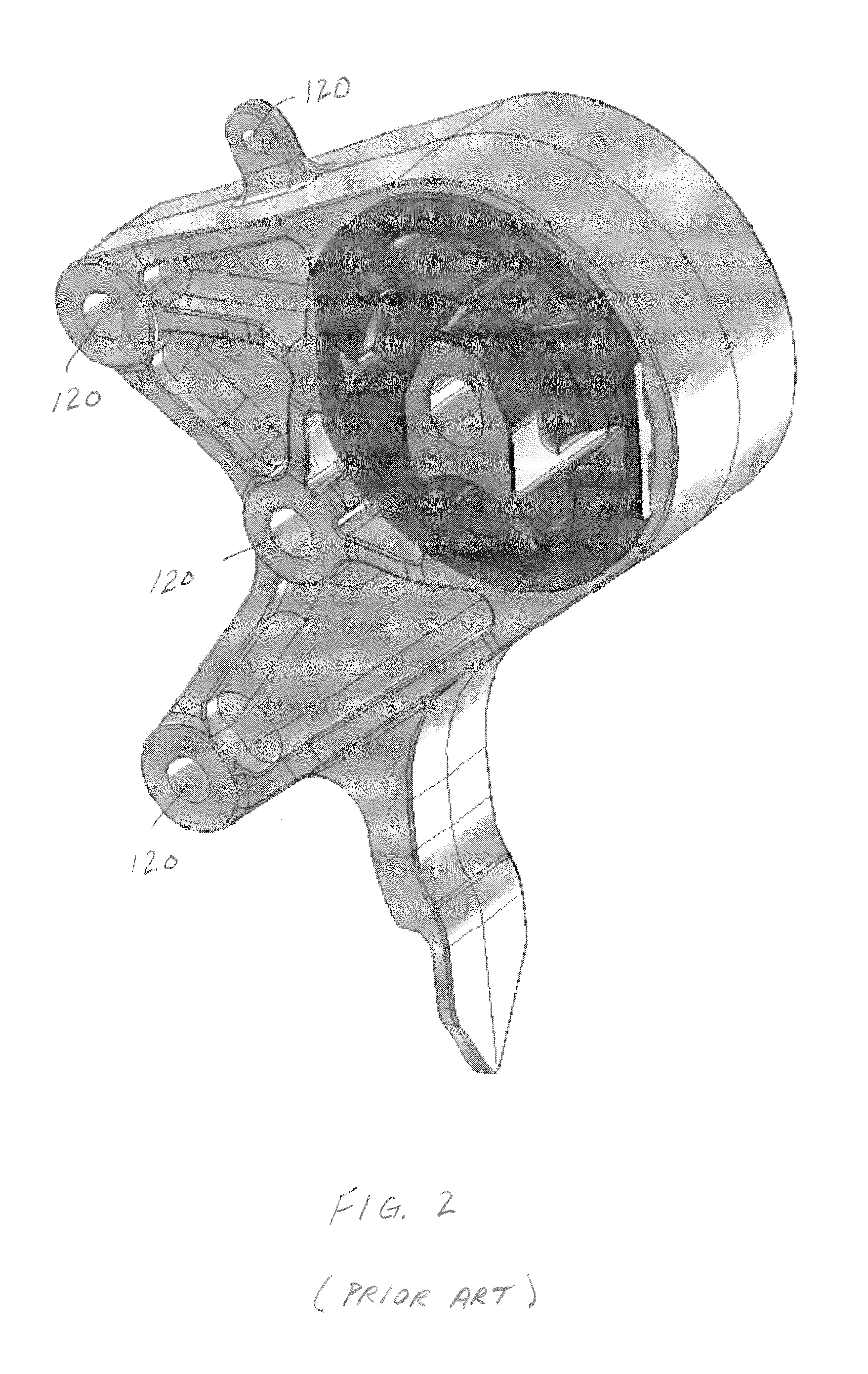
[0027]Turning initially to FIGS. 1 and 2, a torque reacting or engine mount (hereinafter referred to as a mount or engine mount) assembly 100 includes a roll restrictor or bushing (generally referred to as a bushing) 102 received in an outer bracket 104. In a prior arrangement, bushing 102 is typically formed of rubber 106 and may include an insert such as metal insert 108. In this particular embodiment, the metal insert 108 is centrally located in the rubber of the bushing 106. Moreover, the bushing may include one or more cavities at select locations that provide desired areas of relative movement and force damping in a manner well-known in the art.

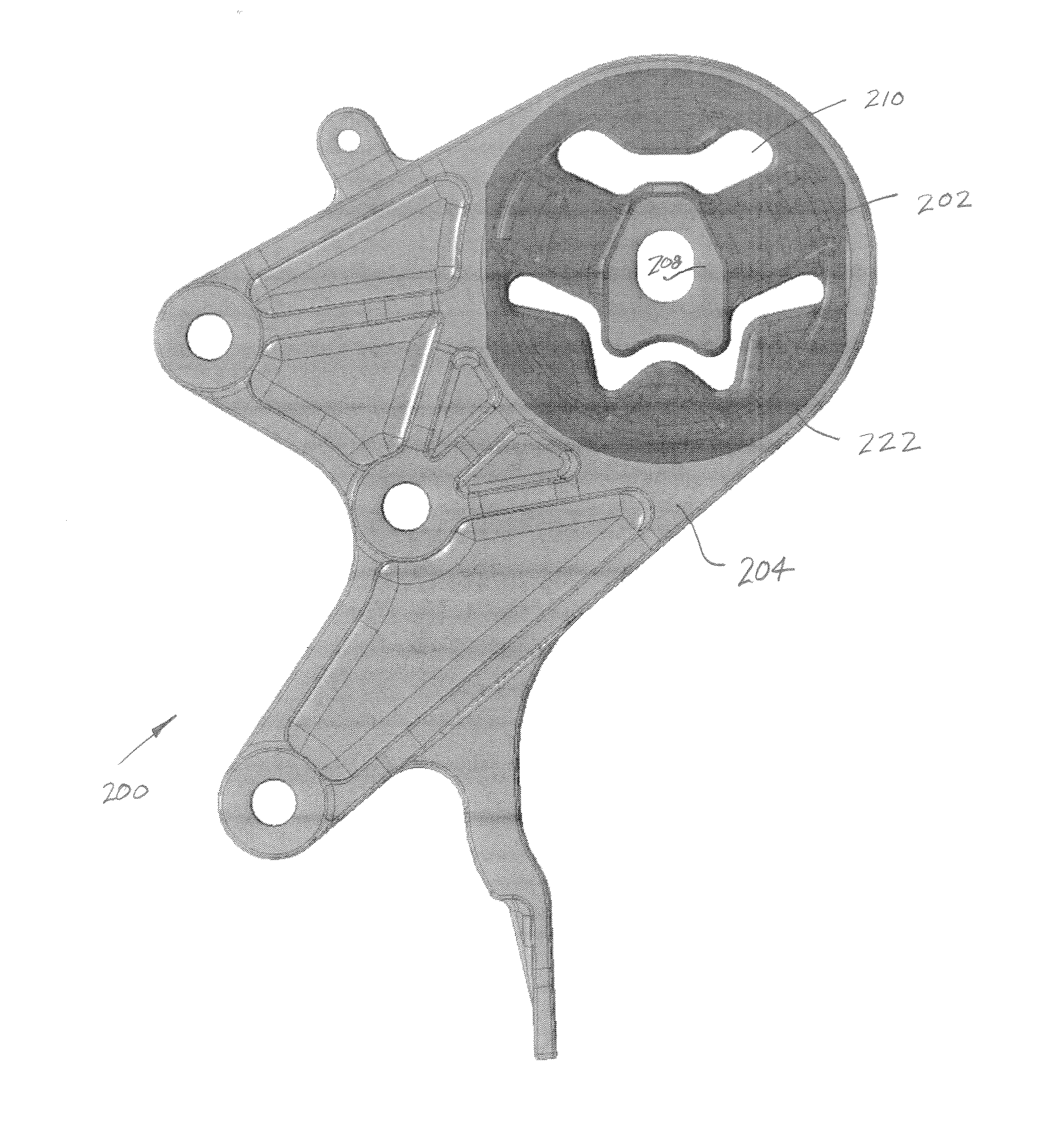
[0028]The bracket 104 is configured for receipt in an associated vehicle and includes one or more fastener receiving openings 120 that receive an associated fastener (not shown) and secure the bracket / engine mount assembly to the vehicle. An opening 122 in the bracket is dimensioned to receive the rubber bushing 102. Typically, the open...


PUM

PropertyMeasurementUnit
moldableaaaaaaaaaa
pressureaaaaaaaaaa
internal stressaaaaaaaaaa

Abstract

A composite encapsulated engine mount includes a rubber bushing having a metal shell received around the bushing. A plastic bracket having a cavity receives the bushing and shell therein. An associated method of forming the mount assembly includes inserting a bushing into a mold, introducing a moldable material into the mold around at least a portion of the bushing to form a bracket, and curing the bracket about the bushing.

Description

BACKGROUND OF THE DISCLOSURE[0001]This application claims priority from U.S. Provisional Patent Application Ser. No. 61 / 143,176, filed 8 Jan. 2009, the disclosure of which is hereby expressly incorporated herein by reference.[0002]This disclosure relates to an engine or torque reacting mount and a method of assembling the mount. Typically, engine mount brackets are made from cast iron, cast aluminum, or stamped steel. A separately made, bushing or roll restrictor is pressed into an opening or cavity in the cast or stamped bracket. The opening is sufficiently smaller so that substantial force is required to press the bushing into the opening.[0003]More recently, composite plastic brackets have been proposed. The mount assembly still incorporates a rubber bushing in the composite bracket. There are two known ways in which the pre-molded rubber bushing is joined to the composite bracket. In the first arrangement, the bushing is pressed into the composite bracket in a manner similar to ...

Claims


Application Information

Patent Timeline
Patent Type & Authority Applications(United States)
IPC IPC(8): F16M13/00F16C33/24B29C45/14
CPCF16F1/3849B60K5/00B60K5/12
Inventor BRADSHAW, JEFF
Owner COOPER STANDARD AUTOMATIVE INC
Why Eureka
Try Eureka