Automotive fuse header assembly

a fuse and header technology, applied in the direction of electrical/fluid circuits, coupling contact parts, vehicle components, etc., can solve the problems of circuit breakage, other difficulties for the fuse to blow, breakage or disruption of power flow, etc., to facilitate soldering, reduce the cross-sectional dimension of the terminal, and large heat capacity

Inactive Publication Date: 2016-10-06
SUMITOMO WIRING SYST LTD
View PDF13 Cites 1 Cited by
  • Summary
  • Abstract
  • Description
  • Claims
  • Application Information

AI Technical Summary

Benefits of technology

[0012]The rear ends of the terminals preferably are narrowed and are configured for insertion into and / or through a conductive through hole in the circuit board. The connecting region at the rear end of each of terminal is narrowed and may have a thickness and a width that are substantially equal. The thickness of the terminal may be uniform throughout the length of the terminal. However, the width of the terminal is narrowed at the end that is connected to the circuit board and may substantially equal the thickness of the terminal. The equal width and thickness facilitates soldering to the circuit board. More importantly, this reduced cross-sectional dimension of the terminal at the circuit board limits the amount of heat that can flow through the terminal and to the busbar or other component upstream of the fuse and fuse header. As a result, the fuses have been found to perform more predictably and in accordance with the specified performance despite the presence of circuits upstream of the fuse with a large heat capacity and the ability to function as a heat sink. The equal thickness and width for the board-connecting portions of the terminals has been found to stabilize the fuse blow characteristics with a simple and versatile design.

Problems solved by technology

Highly sensitive electrically powered components may require a fast blow fuse that will break or disrupt the power flow very quickly in response to a current flow that exceeds the rated current by a specified amount.
Slow blow fuses generally are used with less sensitive electronic components and will cause the circuit to break when the current exceeds the rated current by a specified amount and for a specified duration.
These circuit components with a large heat capacity create uneven temperature rises that cause variations in the time for the fuse to blow or that create other difficulties for the fuse to blow.
A fuse that is not blown at the designated amperage can lead to overheating of the component that is intended to be protected and could cause a thermal event.

Method used


Image

  • Automotive fuse header assembly
  • Automotive fuse header assembly
  • Automotive fuse header assembly

Examples


Embodiment Construction

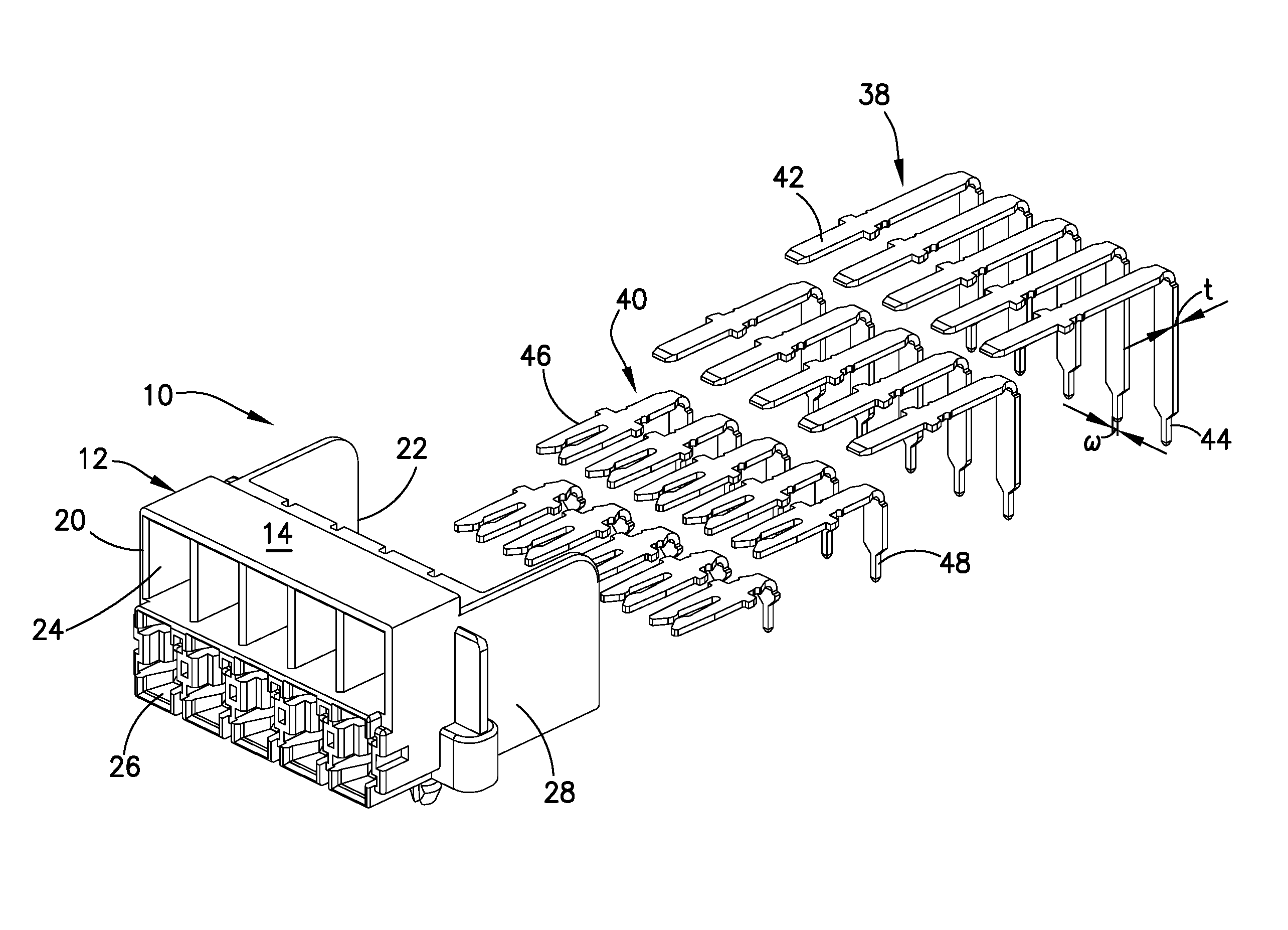
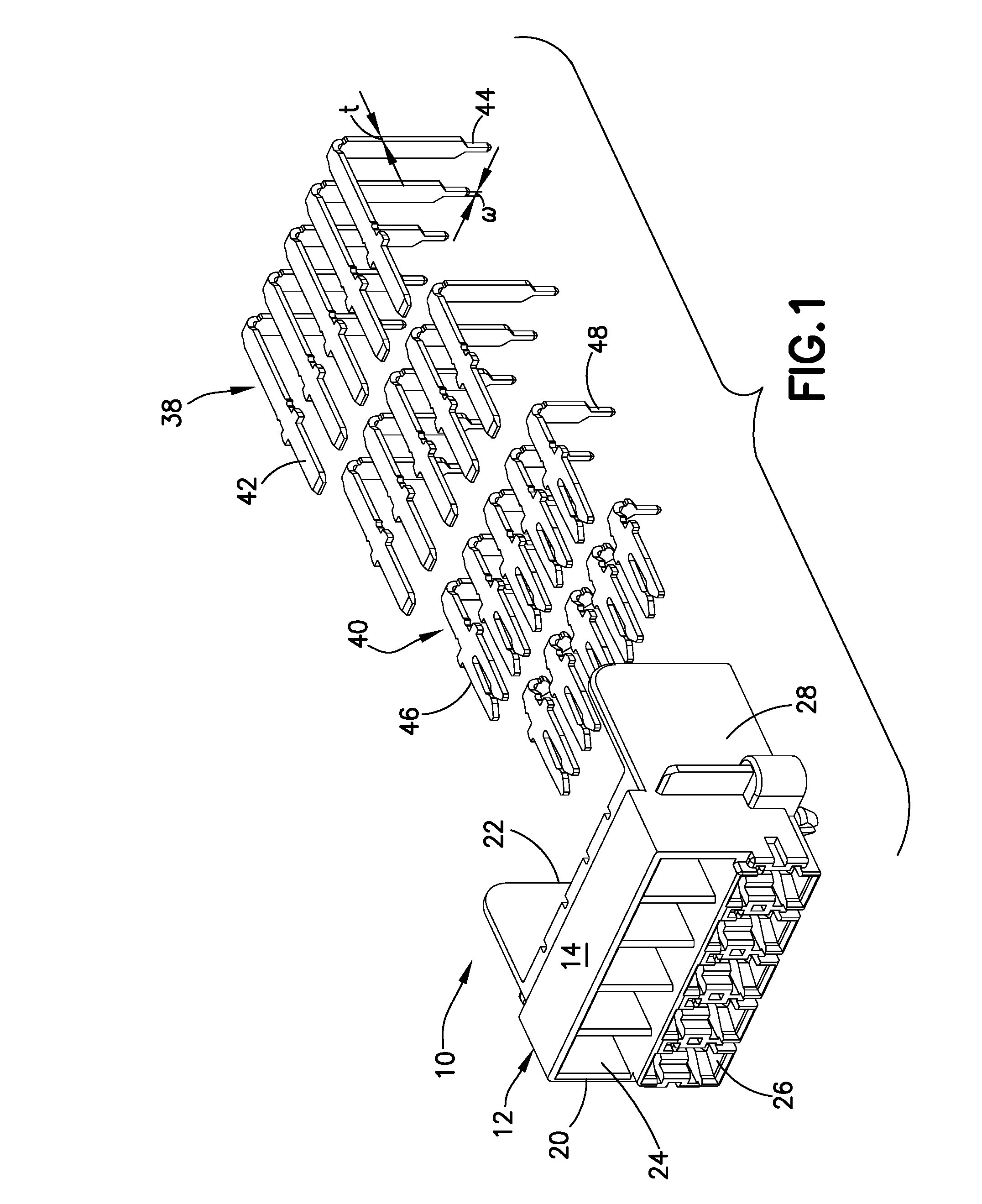
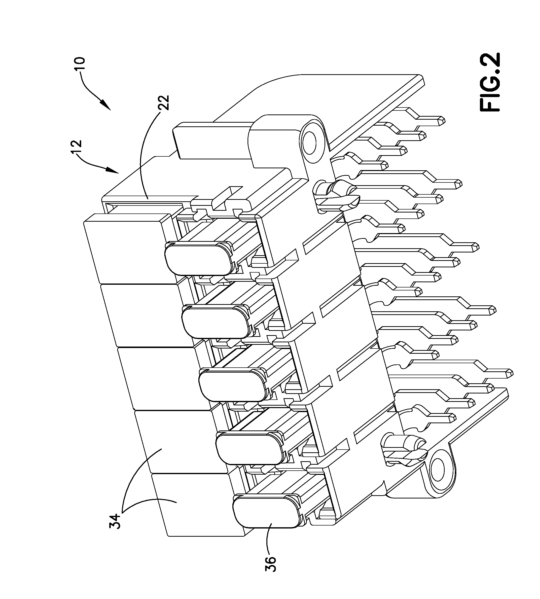
[0020]A fuse header in accordance with an embodiment of the subject invention is identified generally by the numeral 10 in FIGS. 1-4. The fuse header 10 includes a housing 12 with opposite upper and lower surfaces 14 and 16. The lower surface lower surface 16 is to be mounted on a circuit board, and mounting pegs 18 project from the lower surface 16. The mounting pegs 18 are disposed and dimensioned for resiliently locking to mounting apertures in the circuit board.

[0021]The housing 12 has opposite front and rear ends 20 and 22. Upper cavities 24 are disposed in a lateral array in proximity to the upper surface 14 of the housing 12 and lower cavities 26 are disposed in a lateral array in proximity to the lower surface 16 of the housing 12.

[0022]The housing 12 further includes opposite sidewalls 28 and 30 that extend from the front-end 20 of the housing 12 two positions rearward of the rear and 22 of the housing 12. Parts of the sidewalls that project rearward beyond the rear end 22 ...


PUM


Abstract

A fuse header includes a housing with cavities and terminals mounted in the housing adjacent the cavities. Fuses can be mounted removably in the cavities so that the fuses connect to the terminals in the respective cavity. Ends of the terminals opposite the fuses have widths that are narrowed substantially and may equal the thickness of the terminals. The narrow widths impede a flow of heat from the fuse to large conductive regions on a circuit board that could function as a heat sink. Thus, the fuses will provide more reliable protection for components downstream of the fuses.

Description

[0001]This disclosure claims the benefit of priority to U.S. Provisional Application No. 62 / 143,436, filed Apr. 6, 2015, the disclosure of which is incorporated herein in its entirety.BACKGROUND OF THE INVENTION[0002]1. Field of the Invention[0003]The invention relates to a fuse header assembly for a power distribution box or junction box of an automotive vehicle.[0004]2. Description of the Related Art[0005]A power distribution box or junction box for an automotive vehicle distributes power to various electrically powered components of the vehicle, such as the windshield wipers, the fuel pump, the water pump, cooling fans, an air conditioner compressor, power windows, power doors, door locks, power seats, the sound system, the navigation system and various lighting groups. The power distribution block includes at least one fuse header. The fuse header includes a thermoplastic or other resin housing in which fuses are mounted. The fuses are intended to protect the electrically powere...

Claims


Application Information

Patent Timeline
Patent Type & Authority Applications(United States)
IPC IPC(8): B60R16/03H01H85/54
CPCB60R16/03H01H2085/0275H01H85/54B60R16/0238H01H85/2035H01R12/724H01R13/02
Inventor MATSUMURA, AKIHIRO MAX
Owner SUMITOMO WIRING SYST LTD
Why Eureka
Try Eureka