Magnetic resonance imaging using preparation scan for optimizing pulse sequence

a pulse sequence and scanning scan technology, applied in the field of magnetic resonance imaging, can solve the problems of not always true, affecting the optimization of various parameters of the pulse sequence used for imaging scan, and reducing the intensity of the echo signal to be acquired,

Inactive Publication Date: 2003-03-06
KK TOSHIBA
View PDF5 Cites 49 Cited by
  • Summary
  • Abstract
  • Description
  • Claims
  • Application Information

AI Technical Summary

Problems solved by technology

However, it is not always true that an imaging scan for the magnetic resonance imaging is performed under a best imaging condition.
That is, the imaging scan is frequently performed under an unfavorable condition that one or more parameters of a pulse sequence employed by the imaging scan, which influence largely quality of an MR image of an object, has not been optimized.
When the flow void phenomenon is generated in response to a flow of blood, some drawbacks, such as a decrease in the intensity of an echo signal to be acquired, are caused.
However, from a historical viewpoint, the fact is that the optimization of various parameters of a pulse sequence used for an imaging scan, which should be carried out prior to the imaging scan, has not been studied at all.
Hence it has been difficult for an operator to imagine the inside of an object to be examined, and then to recognize a degree of flow void with accuracy in a desired readout direction, before carrying out a three-dimensional scan.
A trail scan could be carried out for inferring a degree of flow void, but this trial scan would not be quantitative.
This technique, however, takes only ECG gating timing into account, so that this way of scanning is far from providing other various scan parameters.

Method used


Image

  • Magnetic resonance imaging using preparation scan for optimizing pulse sequence
  • Magnetic resonance imaging using preparation scan for optimizing pulse sequence
  • Magnetic resonance imaging using preparation scan for optimizing pulse sequence

Examples


Embodiment Construction

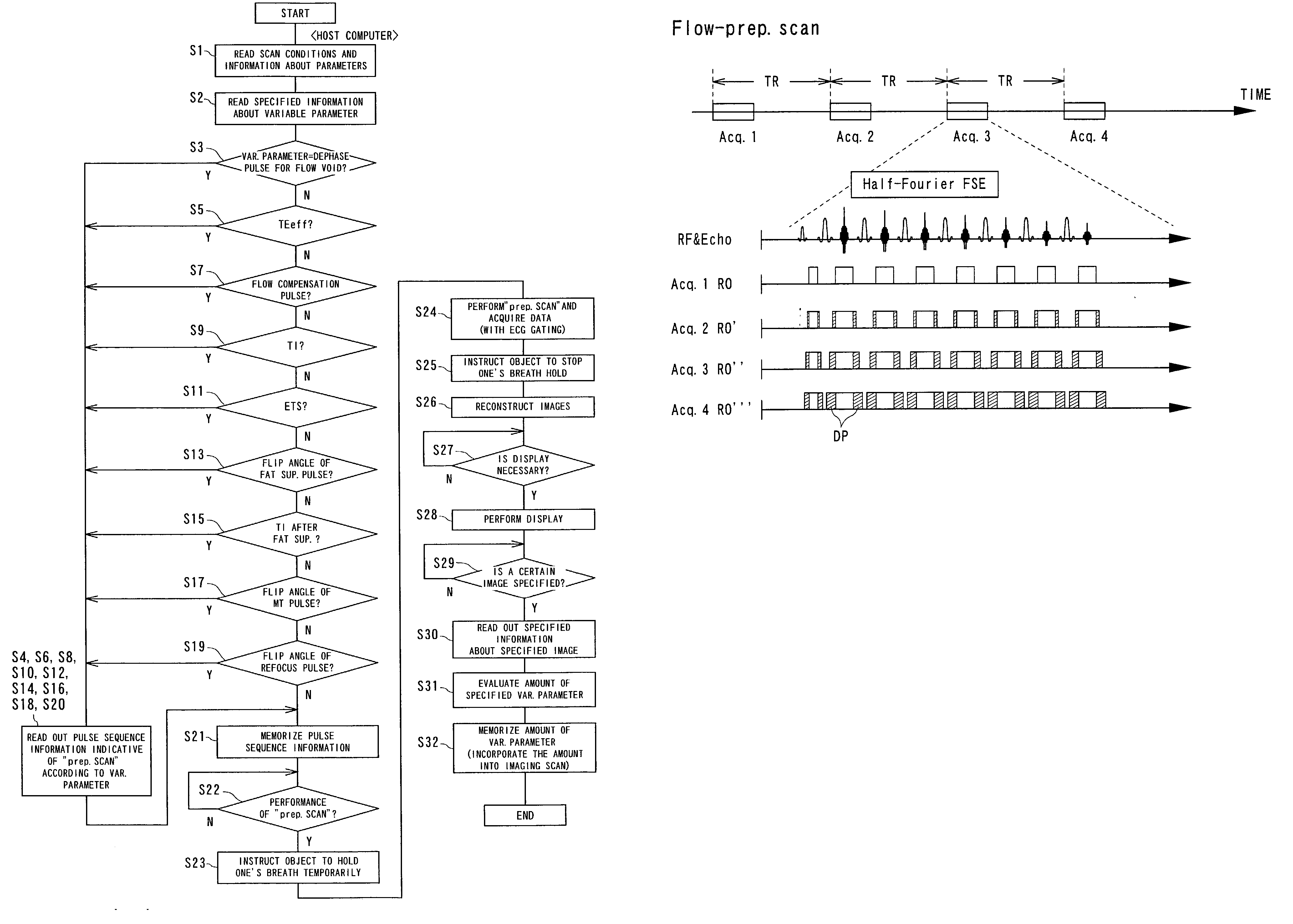
[0039] Referring to FIGS. 1 to 13, a first embodiment of the present invention will now be described.

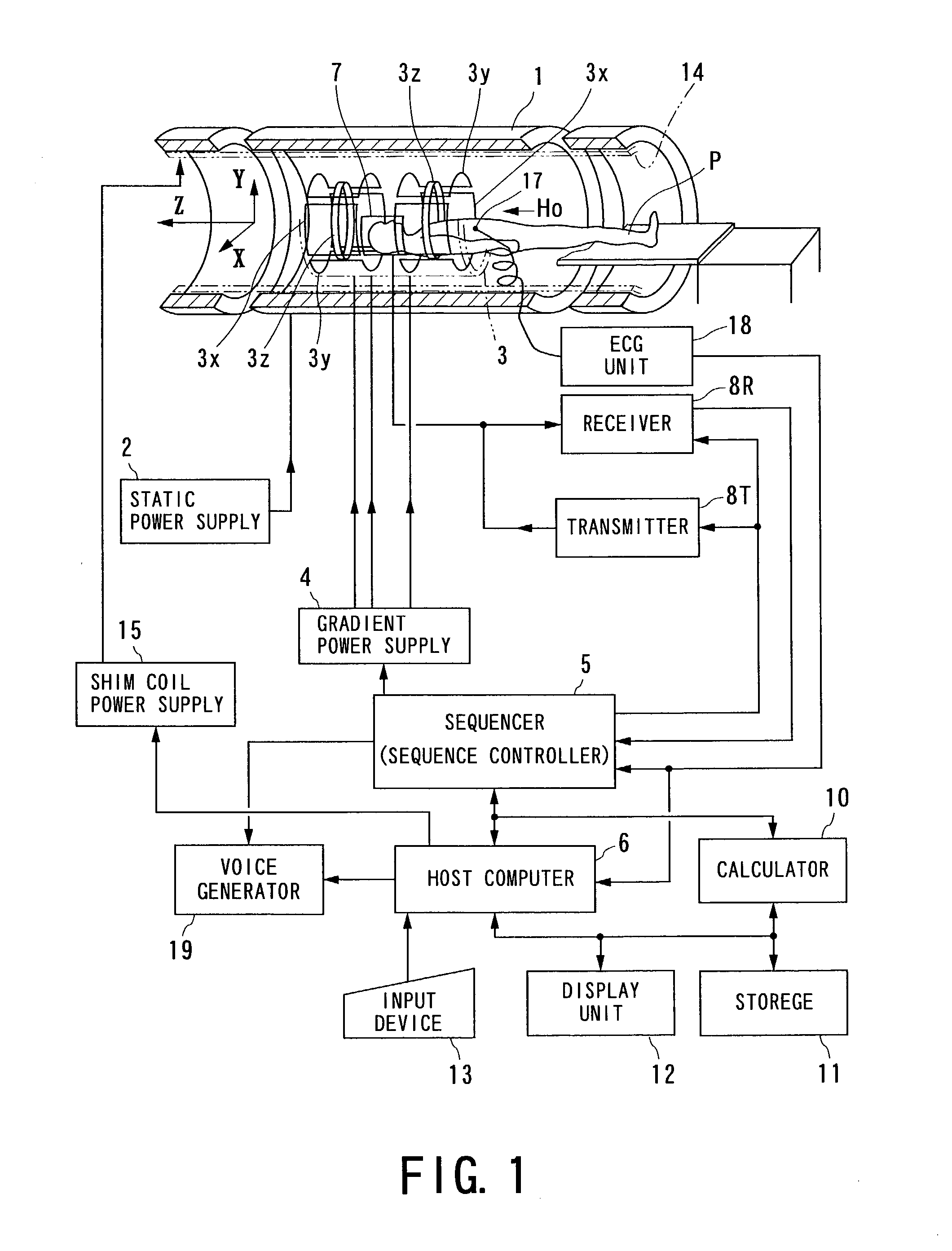
[0040] FIG. 1 a shows an outlined configuration of a magnetic resonance imaging (MRI) system in accordance with the embodiment of the present invention.

[0041] The magnetic resonance imaging system comprises a patient couch on which a patient P as an object to be imaged lies down, static-field generating part for generating a static magnetic field, magnetic-gradient generating part for appending positional information to a static magnetic field, transmitting / receiving part for transmitting and receiving radio-frequency (RF) signals, controlling / calculating part responsible for the control of the whole system and for image reconstruction, electrocardiographing part for acquiring an ECG signal serving as a signal indicative of cardiac phases of the object P, and breath-hold instructing part for instructing the object to perform a temporary breath hold.

[0042] The static-field generating ...


PUM


Abstract

To optimize in advance an amount of a desired parameter incorporated in a pulse sequence performed by an imaging scan, a preparation scan is adopted. The preparation scan is performed with the amount of the desired parameter changed every preparatory image, so that data of a plurality of preparatory images at a desired region of the object can be acquired. For example, such parameter is a TI (inversion time) and its amount is a period of TI. The acquired data are produced into a plurality of preparatory images for display. A desired preparatory image is then selected from the plural preparatory images displayed, and the amount of the desired parameter given from the selected preparatory image is set to the pulse sequence. Hence the desired parameter of the pulse sequence is able to have an optimum amount before actual imaging.

Description

[0001] 1. Technical Field of the Invention[0002] The present invention relates to magnetic resonance imaging for visualizing the internal structures of an object to be imaged on the basis of a magnetic resonance phenomenon of nuclear spins in the object, and in particular, to magnetic resonance imaging, including non-contrast angiography, that uses a preparation scan to optimize a desired parameter of a pulse sequence incorporated in an imaging scan in order to provide MR images with higher fineness.[0003] 2. Related Art[0004] Magnetic resonance imaging (MRI) is generalized as a technique of applying to an object a radio-frequency (RF) signal at a Larmor frequency so that nuclear spins of the object positioned in a static magnetic field are magnetically excited, and reconstructing an image from MR signals induced responsively to the excitation.[0005] However, it is not always true that an imaging scan for the magnetic resonance imaging is performed under a best imaging condition. Th...

Claims


Application Information

Patent Timeline
Patent Type & Authority Applications(United States)
IPC IPC(8): A61B5/055G01R33/58G01R33/48
CPCG01R33/543G01R33/546G01R33/5602G01R33/5613G01R33/563G01R33/5635G01R33/56509G01R33/5673G01R33/583G01R33/586
Inventor MIYAZAKI, MITSUETAKAI, HIROSHI
Owner KK TOSHIBA
Why Eureka
Try Eureka