

Cross-bar switch
a cross-bar switch and switch technology, applied in data switching networks, frequency-division multiplexes, instruments, etc., can solve the problems of difficult to meet timing goals and physical design criteria, large power consumption of traditional cross-bar switches, and complex design
Inactive Publication Date: 2003-03-06
NEXSI SYST
View PDF60 Cites 8 Cited by
- Summary
- Abstract
- Description
- Claims
- Application Information
AI Technical Summary
Benefits of technology
[0018] Additional embodiments of cross-bar switches in accordance with the present invention support variable packet sizes. In one embodiment, the cross-bar switch supports packet sizes ranging from 64 to 9,216 bytes. This feature reduces the need for the system employing the cross-bar to break up packets and re-assemble them to conform with fixed packet size limitations, such as the limitations in traditional cross-bars.
Problems solved by technology
Traditional cross-bars employ a large number of switches, making design complex.
The large number of switches makes it difficult to meet timing goals and physical design criteria.
These traditional cross-bars also consume significant power and circuit space.
The disadvantages associated with a traditional cross-bar are particularly troubling when implementing the cross-bar on an integrated circuit.
The blocked data must be resent at a later time--unnecessarily utilizing processing resources and delaying data transfer.
This inflexibility makes multicasting addressing impossible, unless special multicast circuitry is added.
Without multicast addressing, the processing engine performs multiple packet transfers--wasting both processing resources and system bandwidth.
Support for ensuring quality of service is also inefficient in traditional cross-bars.
This is wasteful when one or more data classes are idle--the buffer memories for the idle data classes go unused.
This puts a significant overhead on the system.
If a sink port detects that a packet fails to meet acceptance criteria, then the sink port does not accept the packet.
If there is an error, the packet will be flagged with an error upon subsequent transmission.
Method used
View moreImage
Smart ImageViewing Examples

Examples
Embodiment Construction
has been presented for purposes of illustration and description. It is not intended to be exhaustive or to limit the invention to the precise form disclosed. Many modifications and variations are possible in light of the above teaching. The described embodiments were chosen in order to best explain the principles of the invention and its practical application to thereby enable others skilled in the art to best utilize the invention in various embodiments and with various modifications as are suited to the particular use contemplated. It is intended that the scope of the invention be defined by the claims appended hereto.
Login to View More PUM
 Abstract
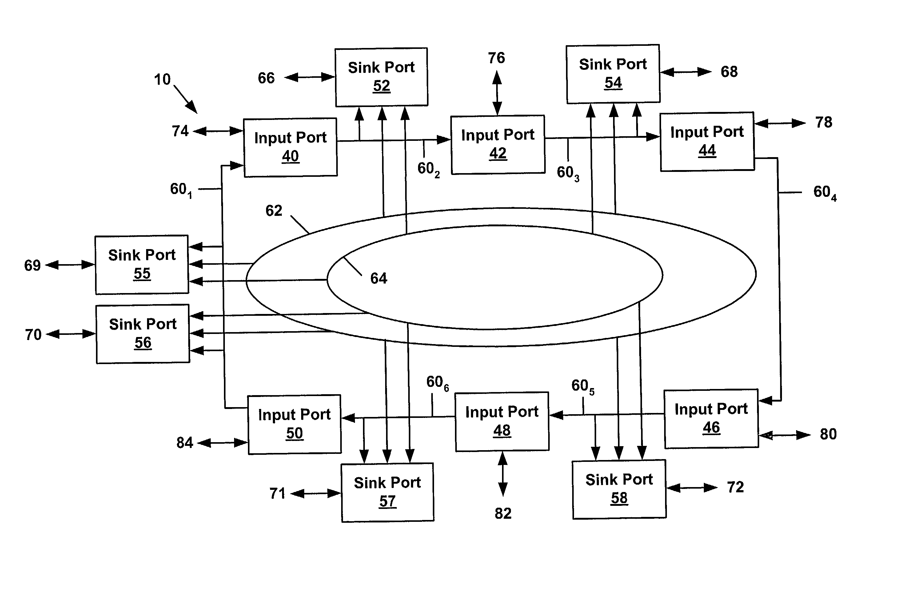
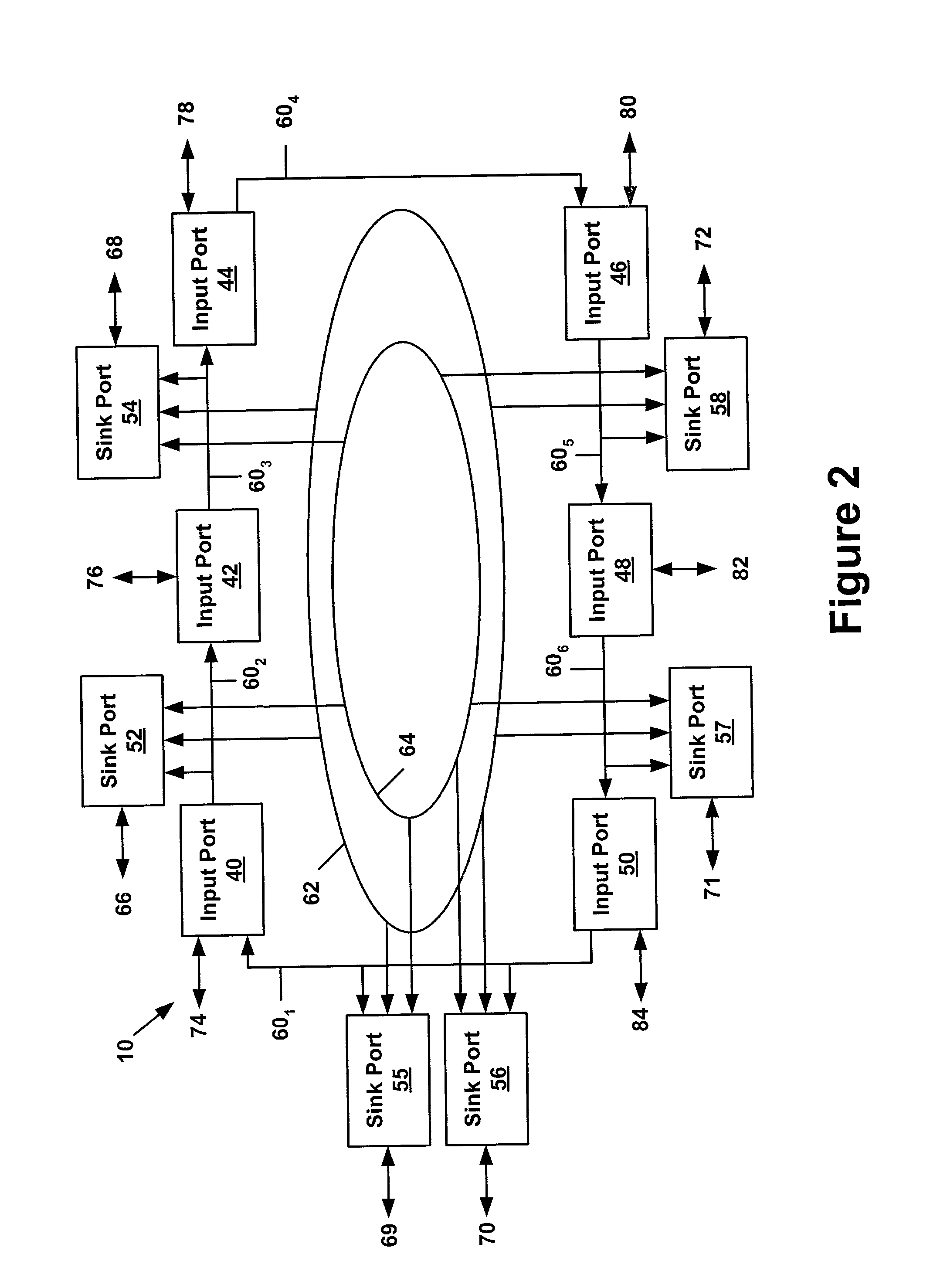
A cross-bar switch includes a set of input ports for receiving data packets and a set of sink ports for transmitting the received packets to identified targets. A set of data rings couples the input ports to the sink ports. Each sink port utilizes the set of data rings to simultaneously accept multiple data packets targeted to the same destination-creating a non-blocking cross-bar switch. Sink ports are also each capable of supporting multiple targets-providing the cross-bar switch with implicit multicast capability.
Description
[0001] 1. Field of the Invention[0002] The present invention is directed to the field of routing data, including the routing of data in a data processing system or communications network.[0003] 2. Description of the Related Art[0004] In data processing environments, multiple data processing engines often require access to the same data. The processing engines pass the data among themselves, until all processing involving the data is complete. In some instances, the processing engines reside in separate systems and transfer data over a communications network. Alternatively, the processing engines all reside in a single system and transfer data over an intra-system network or bus.[0005] A cross-bar facilitates the transfer of data between processing engines by routing incoming data to a target destination. Processing engines send data to the cross-bar with a target destination identifier. The cross-bar determines whether the target is coupled to the cross-bar. If the target is coupled...
Claims
Login to View More Application Information
Patent Timeline
 Patent Type & AuthorityApplications(United States)
IPC IPC(8): H04L12/24H04L12/42H04L12/56
CPCH04L12/42H04L41/0896H04L49/101H04L49/3018H04L49/201H04L49/205H04L49/25H04L49/102
InventorRASHID, ABBASZAIDI, NAZARBRYERS, MARKGRUNER, FRED
OwnerNEXSI SYST