Degree finding instrument

a technology of finding instruments and degrees, applied in the direction of measuring devices, instruments, printing, etc., can solve the problems of inability to achieve functions that cannot be achieved by tools, inferior to those produced with tools, and other directions, to achieve the effect of reducing uncertainty

Inactive Publication Date: 2003-03-20
KRUSE ERNEST W
View PDF0 Cites 19 Cited by
  • Summary
  • Abstract
  • Description
  • Claims
  • Application Information

AI Technical Summary

Benefits of technology

[0036] One of the primary and most significant features of the instant invention described in detail herein is that it alleviates uncertainties when attempting to determine angles and miters for the precise installation of trim and molding to walls and ceilings.

Problems solved by technology

Since the most ancient days of mankind, man has utilized instruments and tools to perform tasks that would be otherwise nearly impossible or very difficult to perform.
Even if the task or work could be performed without using tools, at the very least, the results would be inferior to those produced with tools.
In fact, some tools perform functions that simply cannot be achieved without the use of that particular tool, or, may require the use of a similar tool.
In dealing with the relatively uncomplex matter of measuring the distance between two points, it is impossible to precisely measure such distance without a scale.
It is simply not possible to accurately measure a distance without such a scale, because there is no reference or starting point.
However, this is inherently inaccurate.
This measuring device is limited for use in the measurement of inclined exterior, or outside, angles.
It does not teach the use of this instrument in the measurement of inside angles.
Additionally, measurement errors will develop as the detachable wear tips 19 and 20 wear, and / or in addition as their respective mounting screws become loose.

Method used


Image

  • Degree finding instrument
  • Degree finding instrument
  • Degree finding instrument

Examples


Embodiment Construction

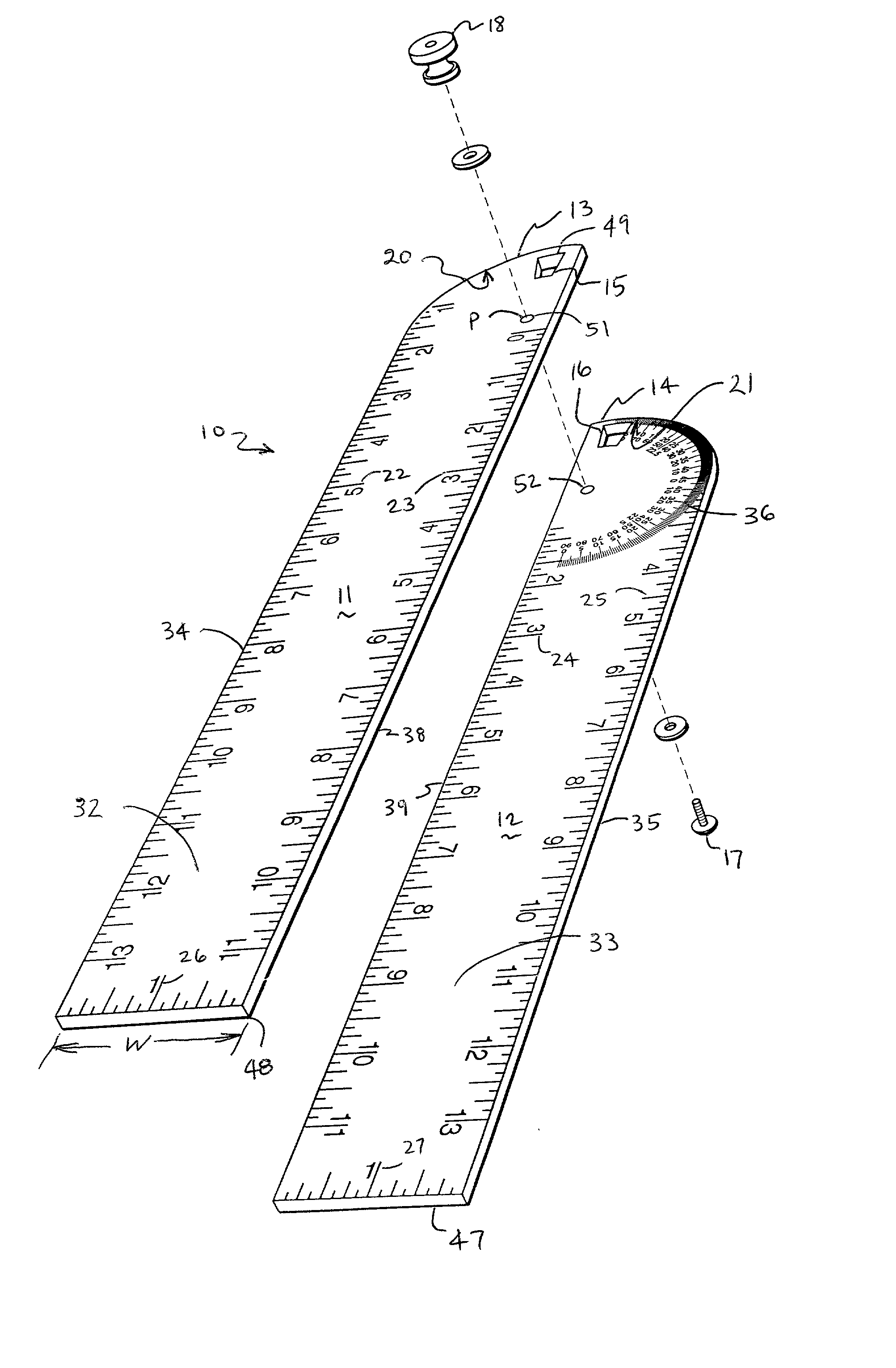
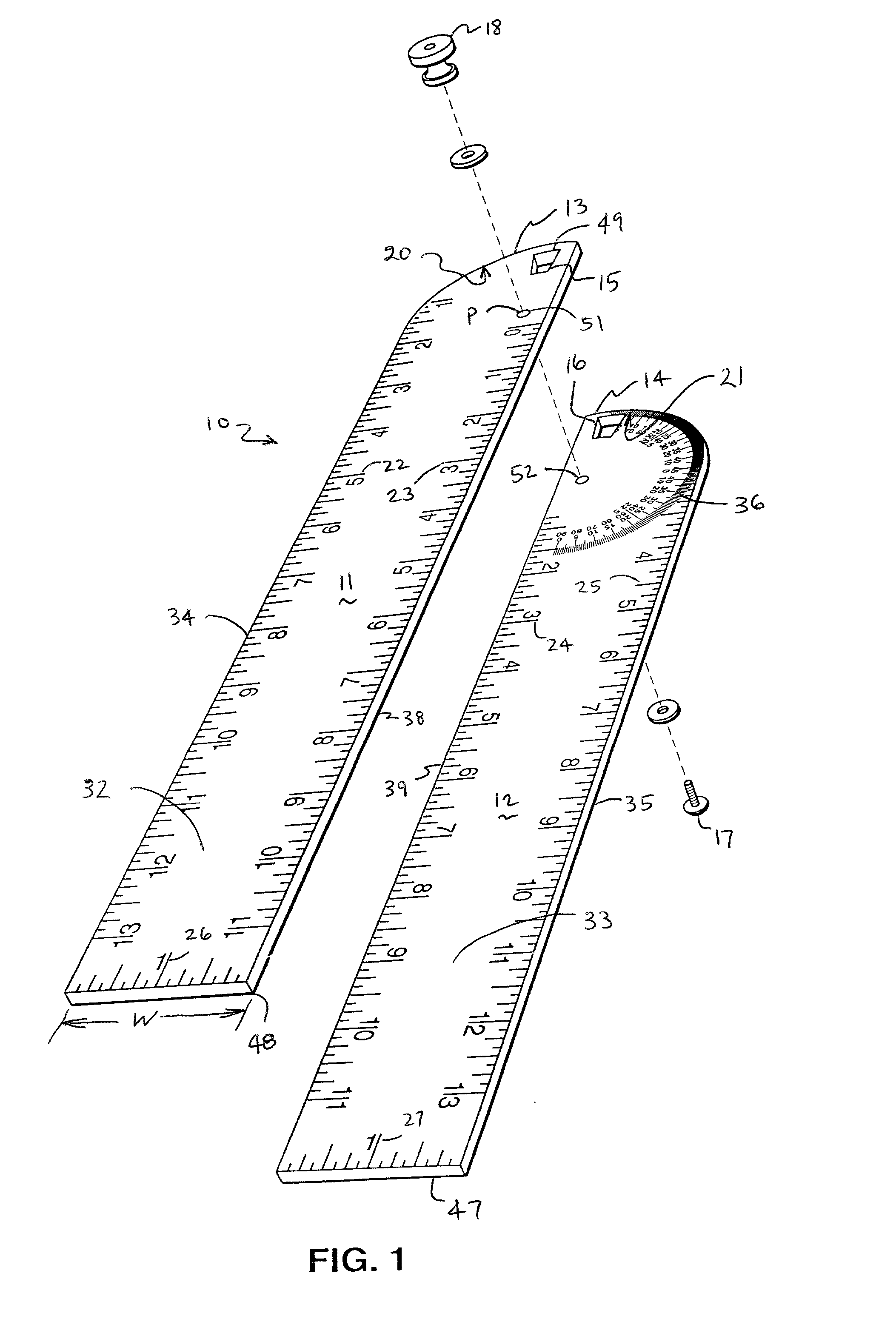
[0048] With regards to all of the drawings herein, and with specific emphasis now to FIG. 1, there is shown the present invention an improved combination degree finding and linear measuring instrument 10 for directly indicating the degree, or angle, to be used for cutting and thereafterwards joining of the cut material items is disclosed, consisting of a pair of blade-shaped arms 11, 12 pivotally secured to each other at the ends 13, 14 by means of a pair of complementary apertures 15, 16 with a bolt 17 and nut 18 combination.

[0049] As specifically illustrated in FIG. 3, the first arm 11 and the second arm 12 are joined together in variable angular relationship. The first arm 11 and the second arm 12 are preferably joined together in pivotal relationship to each other typically by means of a bolt 17 and nut 18 combination. Of course, the bolt 17 and nut 18 combination could readily be substituted with a pin or rivet combination which is equivalent to the function of the bolt 17 and ...


PUM


Abstract

A improved combination degree finding and linear measuring instrument for directly indicating the degree, or angle, to be used for cutting and thereafterwards joining of the cut material items is disclosed, consisting of a pair of blade-shaped arms pivotally secured to each other at one end thereof to matingly conform to the inside or the outside engaged angle corresponding to the angle of the two pieces of the material which are to be joined. The true angle for accurately and precisely mating the material items to be cut is directly determined based upon a precise measurement of the pair of blade-shaped arms directly read as true angle measured which is indicated through an first offset sight aperture disposed over a first 180 degree scale and one-half of the angle indicated through the first offset sight aperture is indicated through a second offset sight aperture on the second 180 degree scale located on the opposite side of the instrument from the first offset sight aperture and the first 180 degree scale. Each of the arms includes measuring scales thereon for use as a ruler. The pair of blade-shaped arms are pivotally secured at one end of the pair of blades and can be pivotally adjusted to arrange the pair of arms to form a single long measuring arm at 180 degrees and locked into position by the threaded set screw and nut used to pivotally secure the pair of blades together. In fact, the pair of blades can be pivotally adjusted to form any angle between the blades.

Description

[0001] 1. Field of the Invention[0002] The present invention relates to an degree finding device, and, more particularly, to measuring devices used to indicate angles between lines, surfaces and the like, such as the number of degrees engaged by the degree finding instrument and the angle indicated by the instrument can be read directly or determined by calculation via a differential measurement accomplished by this degree finding instrument.[0003] 2. Description of the Prior Art[0004] Since the most ancient days of mankind, man has utilized instruments and tools to perform tasks that would be otherwise nearly impossible or very difficult to perform. Even if the task or work could be performed without using tools, at the very least, the results would be inferior to those produced with tools. Tools are typically designed to make a difficult job easier to perform. Oftentimes, the work to be performed can be accomplished more quickly and a much better result achieved by the utilization...

Claims


Application Information

Patent Timeline
Patent Type & Authority Applications(United States)
IPC IPC(8): B26B29/06
CPCB26B29/06G01B3/563
Inventor KRUSE, ERNEST W.
Owner KRUSE ERNEST W
Why Eureka
Try Eureka