

Method of decontaminating by ozone and a device thereof
- Summary
- Abstract
- Description
- Claims
- Application Information
AI Technical Summary
Benefits of technology
Problems solved by technology
Method used
Image

Examples
first embodiment
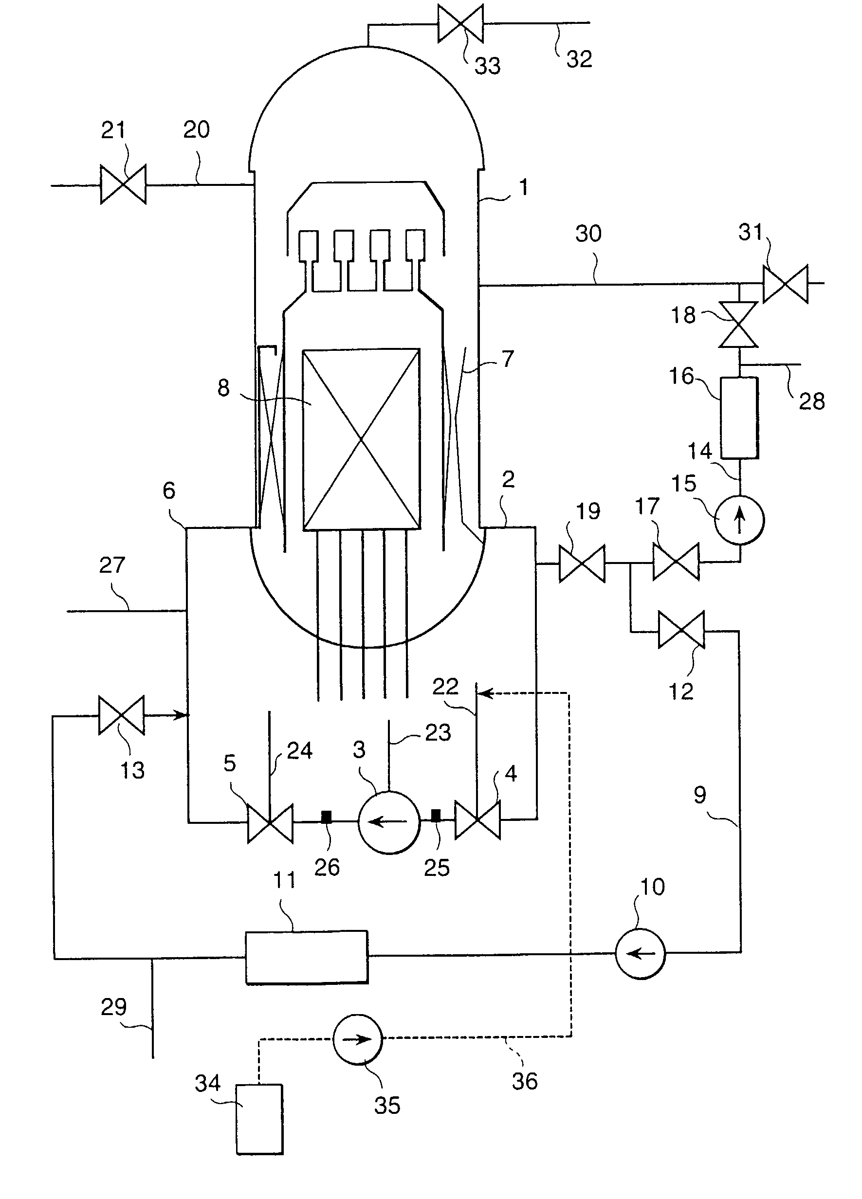
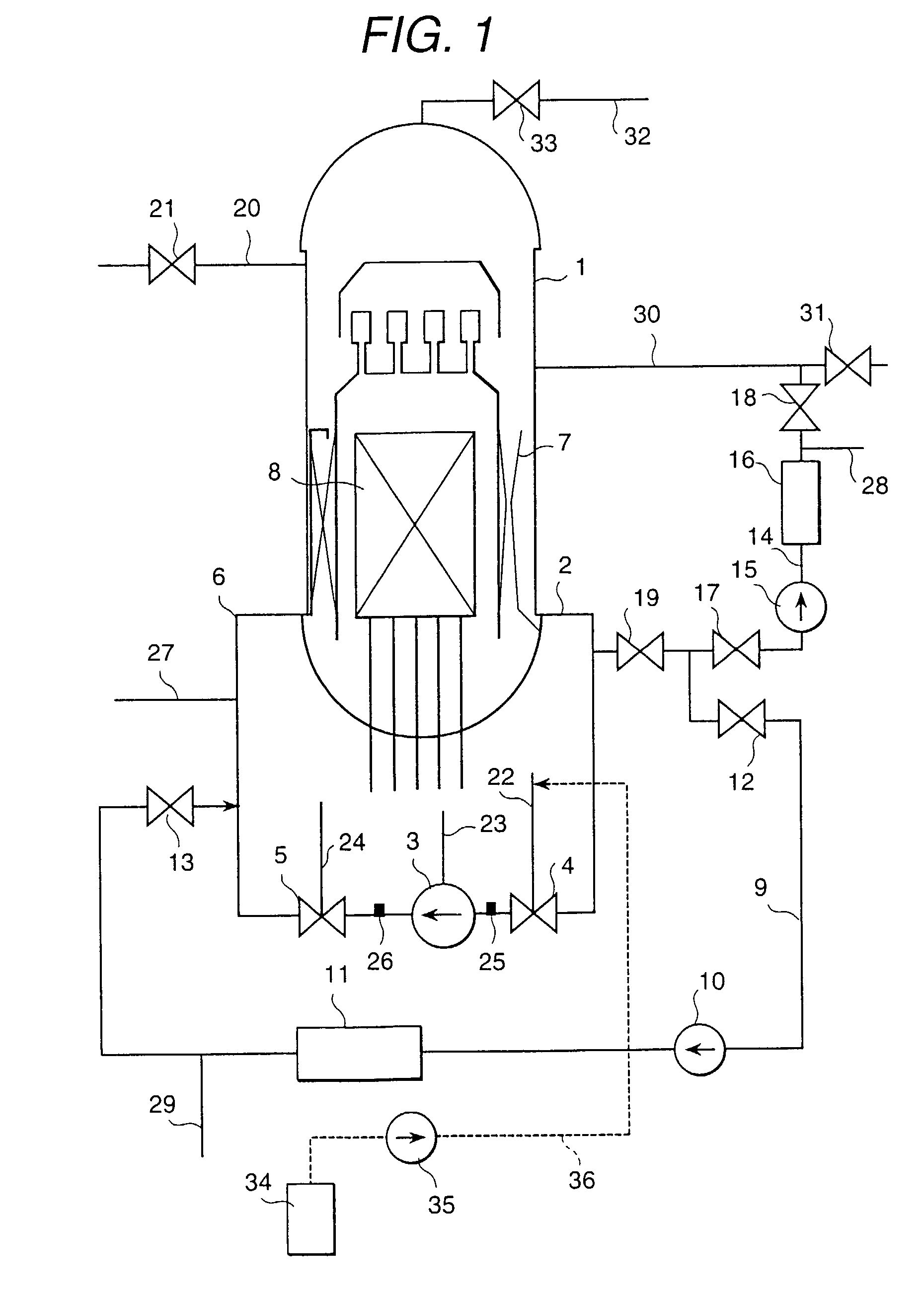
[0021] Below will be explained the present invention, referring to FIG. 1. This embodiment applies a device in accordance with the present invention to decontaminate the inner surfaces of units and pipes in the reactor water re-circulation system of a boiling water type nuclear power plant. FIG. 1 is a decontaminating system example comprising a reactor pressure vessel, a reactor water re-circulation system, a reactor water clean up system, a residual heat removal system, and a device or supplying an ozone gas (which is prepared by evaporation of liquid ozone) to these systems.
[0022] This embodiment provides an ozone decontaminating device which comprises an ozone gas supplying unit 34, an ozone gas supplying line 36 having one end connected to the ozone gas supplying unit 34 and the other end connected to a vent line 22 of the inlet valve 4 of the re-circulation system, and an ozone gas supply pump 35 which is placed in the ozone gas supplying line 36 and feeds the ozone gas from o...
fourth embodiment
[0067] Referring to FIG. 7, the decontaminating device which is the present invention comprises
[0068] a decontamination tank 62,
[0069] a circulation line 62 which has both upstream and downstream ends connected to opposite ports of the decontamination tank 61 and contains a circulation pump 63, a valve 66, an ozone decomposing column 57, an ion exchange resin column 58, an ozone dissolving tank 53 in the order from upstream to downstream,
[0070] a bypath line 64 which connects one part of the circulation line 62 between the circulation pump 63 and the valve 66 to the another part of the circulation line 62 between the ion exchange resin column 58 and the ozone dissolving tank 53,
[0071] an ozone gas decomposing column 59 which is connected to the ozone dissolving tank 53 with a vent line 68,
[0072] a vent line 60 which connects the ozone dissolving tank 53 and the vent line 68,
[0073] an ozone gas supplying unit 34,
[0074] an ozone gas supplying line 36 which connects the ozone gas suppl...
embodiment 4
[0076] For decontamination, the device of Embodiment 4 takes the steps of filling the decontamination tank 61 with water as a fluid for decontamination, putting the contaminated units and parts in the decontamination tank 61, opening the valve 65 and closing the valve 66 to accelerate elution of radioactivities with high-concentrated ozone, running the circulation pump 63 in the circulation line 6 to flow water to and from the decontamination tank 61 through the circulation line 62, and feeding ozone from the ozone gas supplying unit 34 to the ozone dissolving tank 53 to make ozone-rich water. The excessive gas decomposed in the ozone gas decomposing column 59 is exhausted through the vent line 60 of the ozone dissolving tank 53.
[0077] The ozone-rich water prepared in the ozone dissolving tank 53 oxidizes and elutes radioactive materials deposited on the surfaces of contaminated units and parts in the decontamination tank 61 while the ozone-rich water allows through the decontaminat...
PUM
 Abstract
Description
Claims
Application Information