Ice cream machine having an auxiliary evaporator tank

a technology of ice cream machines and evaporators, which is applied in the direction of mechanical equipment, refrigeration components, lighting and heating equipment, etc., can solve the problems of disadvantage of prior art ice cream machines, uneven cooling and less efficient efficiency of partially filled evaporators

Inactive Publication Date: 2003-04-03
STOELTING
View PDF0 Cites 12 Cited by
  • Summary
  • Abstract
  • Description
  • Claims
  • Application Information

AI Technical Summary

Problems solved by technology

Since most heat transfer occurs when the liquid refrigerant is changed to vapor, the partially filled evaporator is less efficient than a flooded evaporator (e.g., an evaporator filled entirely with liquid refrigerant).
The partially filled evaporator also tends to unevenly cool the ice cream because the parts of the evaporator which are filled with vapor are not able to cool as effectively as the parts of the evaporator filled with liquid.
Further, prior art ice cream machines are disadvantageous because the pressure does not remain constant in the evaporator due to the accumulation of vapor.
The inefficiencies resulting from the partially filled evaporator require the ice cream machine to use a larger, more expensive, and less energy efficient condenser or pump.

Method used


Image

  • Ice cream machine having an auxiliary evaporator tank
  • Ice cream machine having an auxiliary evaporator tank
  • Ice cream machine having an auxiliary evaporator tank

Examples


Embodiment Construction

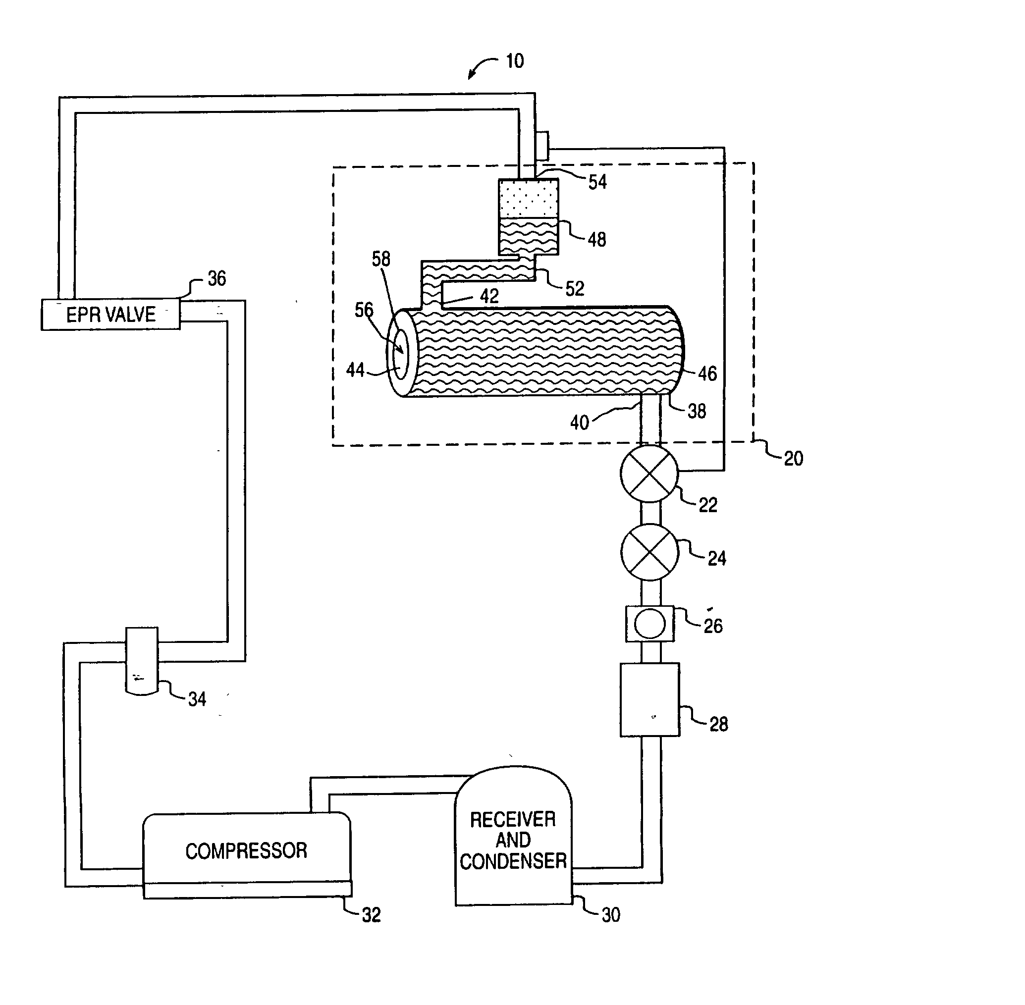
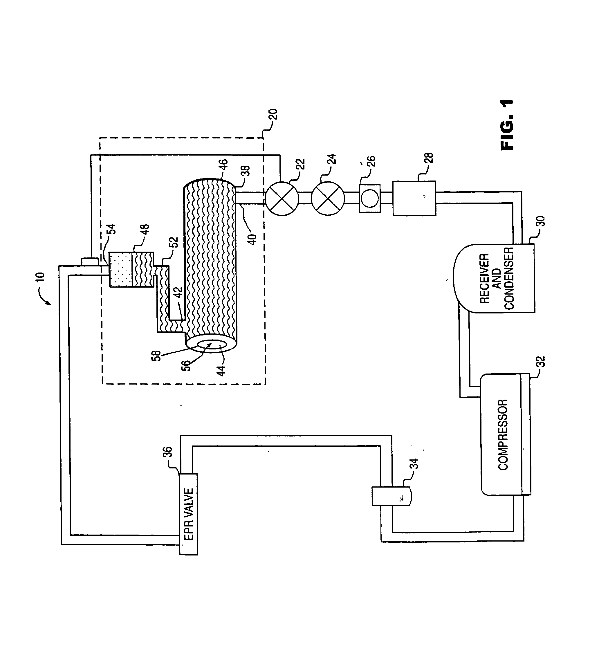
[0016] A cooling system or ice cream machine 10 is diagrammatically shown in FIG. 1. Ice cream machine 10 includes an evaporator 20, an expansion valve 22, a solenoid valve 24, a sight glass 26, a filter 28, a condenser 30, a compressor 32, an accumulator 34, and a valve 36. Evaporator 20 includes a cylindrical cooling tank 38 and an auxiliary tank 48.

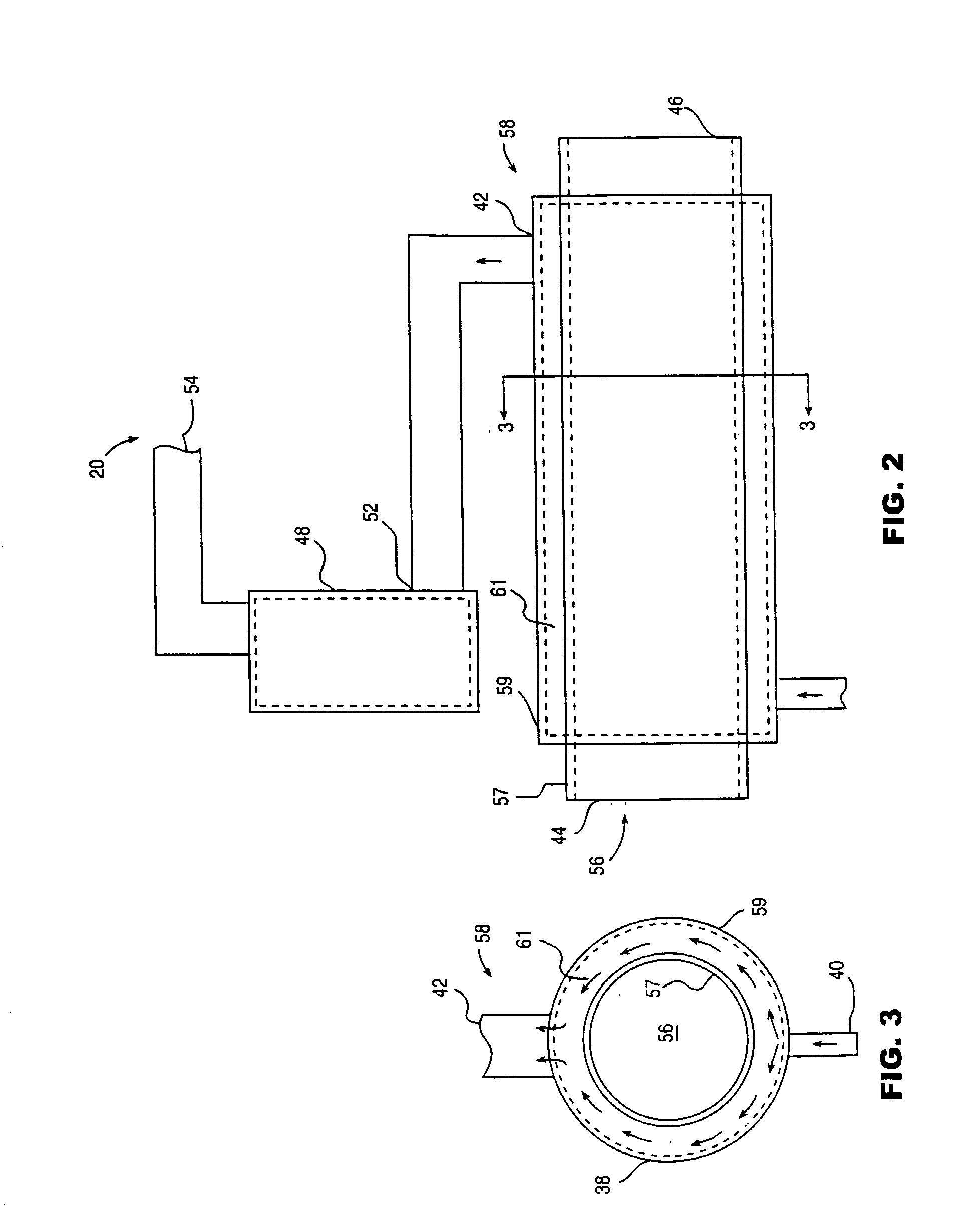
[0017] Cylindrical cooling tank 38 includes a refrigerant input 40, a refrigerant output 42, a liquid ice cream input 44, and a solid ice cream output 46. Auxiliary tank 48 includes a liquid refrigerant input 52 and a vapor refrigerant output 54. Cylindrical cooling tank 38 includes a cooling chamber 56 defined by an interior surface or wall 58 of tank 38.

[0018] Auxiliary tank 48 is positioned above with respect to gravity or over cylindrical cooling tank 38. Additionally, liquid refrigerant input 52 is located above refrigerant output 42, and refrigerant input 40 of tank 38 is located beneath refrigerant output 42 of tank 38. Vapor re...


PUM


Abstract

An ice cream machine for cooling liquid ice cream into frozen ice cream includes an evaporator having a cylindrical cooling tank and an auxiliary tank. The auxiliary tank ensures that the cylindrical cooling tank is flooded with liquid refrigerant during normal operation. The flooding of the cylindrical cooling tank provides more efficient and even cooling in an interior cooling chamber. The more efficient cooling allows the ice cream machine to utilize a smaller compressor, thereby reducing the cost and energy consumption of the ice cream machine. The auxiliary tank can be a coil of tubing or a cylindrical container positioned above the cylindrical cooling tank.

Description

CROSS-REFERENCE TO RELATED PATENT APPLICATIONS[0001] 1. Field of the Invention[0002] The present invention relates to refrigeration or cooling systems. More particularly, the present invention relates to an ice cream machine having an auxiliary evaporator tank.[0003] 2. Background of the Invention[0004] Ice cream machines as well as other systems for cooling or freezing food stuffs, condiments, or other materials, typically include an evaporator situated proximate the material being chilled. For example, in ice cream machines, liquid ice cream is typically inserted in a freezing chamber adjacent the evaporator and is removed from the freezing chamber as solid or semi-solid ice cream. The evaporator removes heat from the freezing chamber as a liquid refrigerant such as FREON.RTM., ammonia, HP62, 502 or other liquid having a low boiling point changes to vapor in response to the heat from the liquid ice cream. Typically, the evaporator is partially filled with vapor as the liquid refri...

Claims


Application Information

Patent Timeline
Patent Type & Authority Applications(United States)
IPC IPC(8): A23G9/08A23G9/14A23G9/16A23G9/22A23L3/36F25B39/02F25B40/00F25B41/06F25B49/02
CPCA23G9/08A23G9/14A23G9/16A23G9/22A23G9/225A23L3/36F25C2600/04F25B40/00F25B41/062F25B49/022F25B2339/0242F25B2500/05F25B39/02F25B41/31
Inventor ROSS, HAROLD F.
Owner STOELTING
Why Eureka
Try Eureka