Belt-type particleboard press

a belt-type, particleboard technology, applied in the dryer section, dough-sheeters/rolling machines/rolling pins, dryers with progressive movements, etc., can solve the problems of overstressed edge region belt failure, large disadvantage, and exposed rollers at their ends, so as to prolong the service life

a belt-type, particleboard technology, applied in the dryer section, dough-sheeters/rolling machines/rolling pins, dryers with progressive movements, etc., can solve the problems of overstressed edge region belt failure, large disadvantage, and exposed rollers at their ends, so as to prolong the service life

US20030066441A1Inactive Publication Date: 2003-04-10SIEMPELKAMP MASCH & ANLAGENBAU GMBH & CO KG

Image

  • Belt-type particleboard press
  • Belt-type particleboard press
  • Belt-type particleboard press

Examples


Embodiment Construction

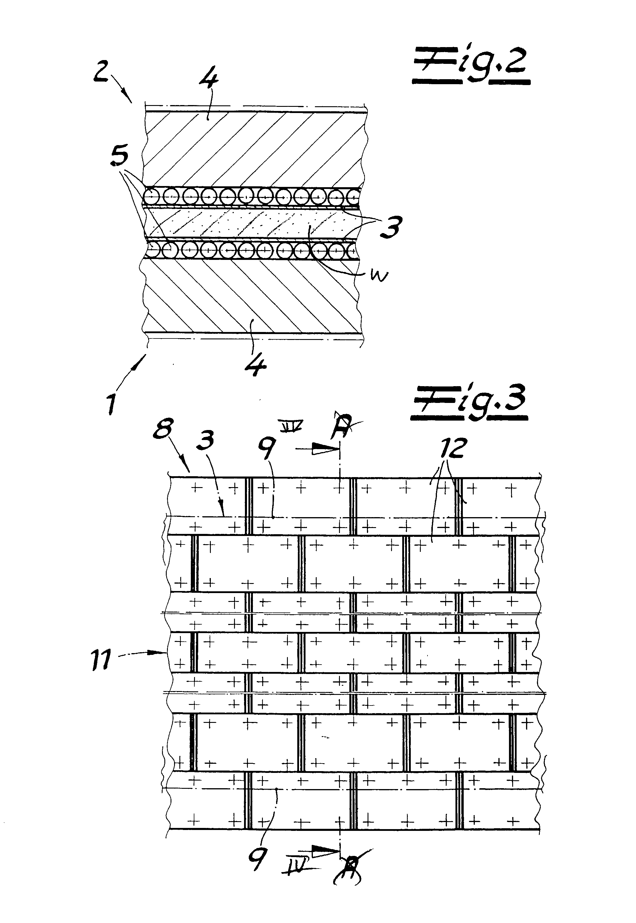
[0023] A belt has a length l of 65 m and the working stretches in actual contact with the workpiece W have a length of 40 m. There is a temperature differential .DELTA.T of 80.degree. C. between the hot center region 11 and the cooler edge strips 9. This produces in the edge strips 9 a stretch .epsilon. as follows:

.epsilon.=.alpha..multidot..DELTA.T==11.multidot.10.sup.-6.multidot.80.deg-ree.=8.8.multidot.10.sup.-4.

[0024] Hence

.epsilon.=.DELTA.l / l.gtoreq..DELTA.l=8.8.multidot.10.sup.-4.multidot.40 m=35 mm.

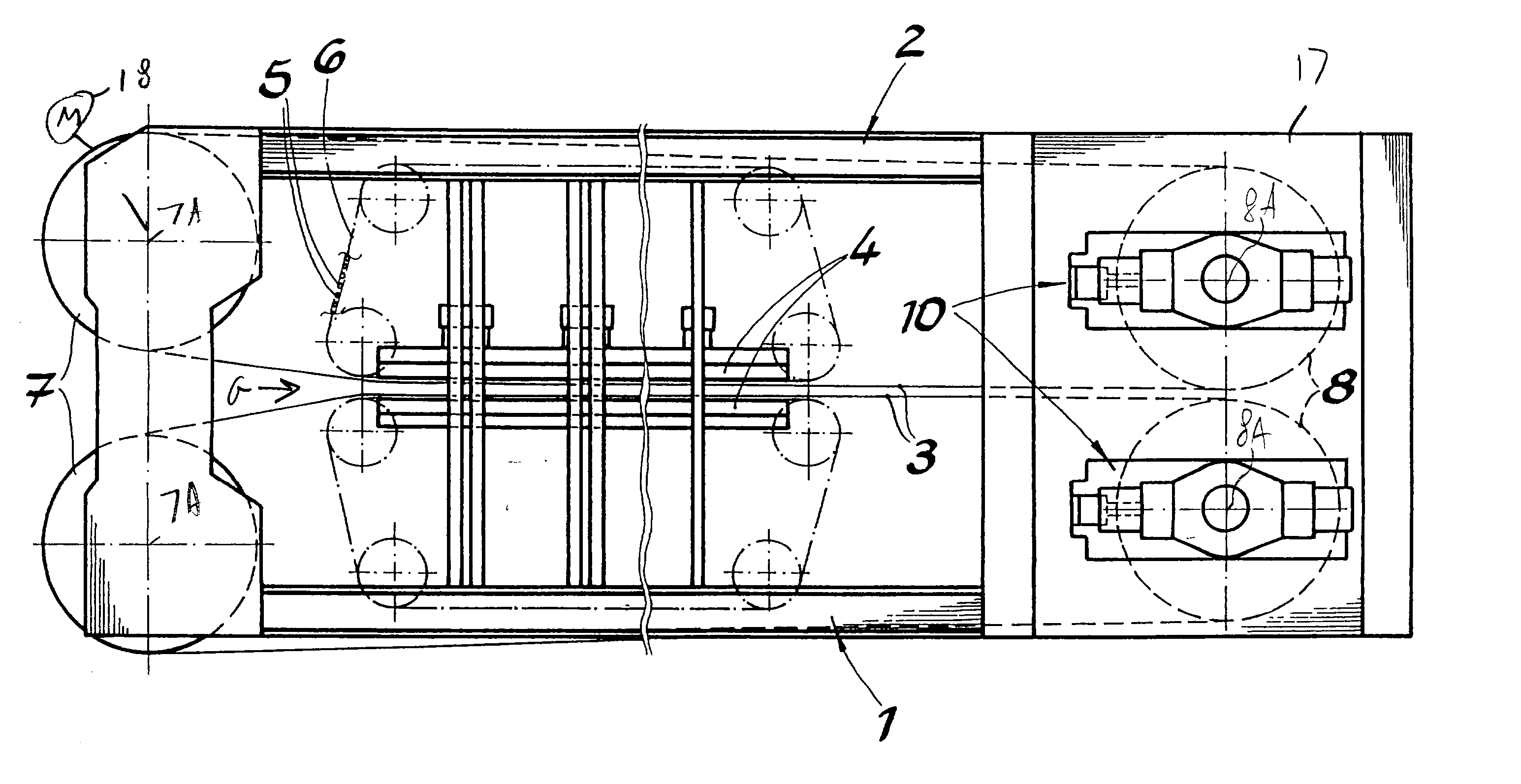
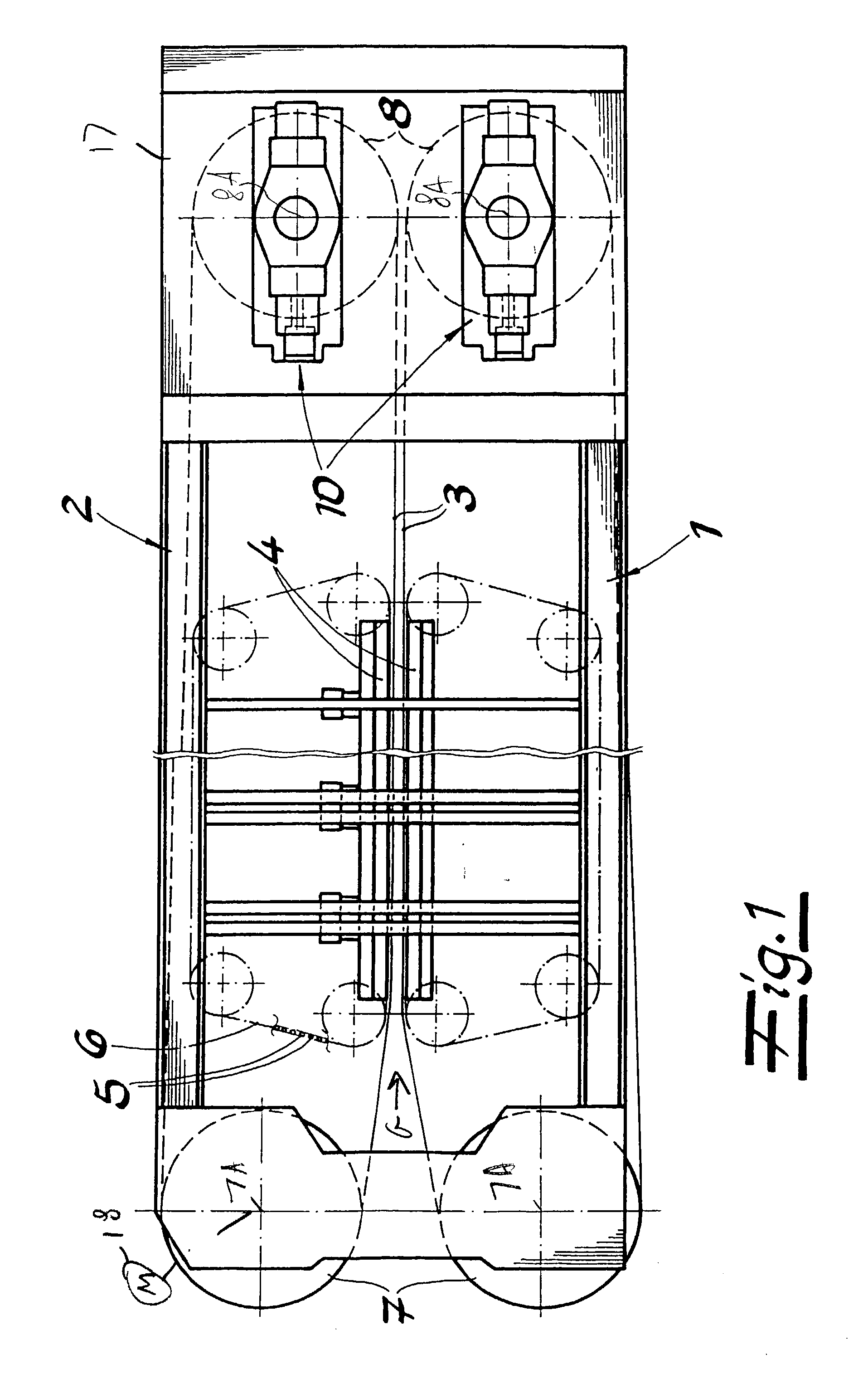
[0025] The drums 7 and 8 have a diameter D of 2950 mm producing a circumference .phi. as follows:

.phi.=.pi. D=9267 mm.

[0026] The belts 3 are only looped around half, that is 180.degree., of the drums 7 and 8 so that

.phi. / 2=4633 mm.

[0027] Since the colder and shorter belt edges 9 the circumference .phi. of the drums 7 and / or 8 where they contact these edges 9 must be

4633 mm-35 mm=4598 mm.

[0028] This corresponds to a diameter of 2972 mm at the formations 12, some 23 mm smaller in dia...


PUM


Abstract

A continuous belt press has upper and lower platens defining a horizontal gap. Upper and lower upstream drums and downstream are rotatable on the frame about respective horizontal drum axes at the upstream and downstream ends of the gap. Upper and lower endless steel belts spanned over the respective upper and lower drums each have a working stretch supported by respective upper and lower sets of rollers on the respective platens. Each belt has a pair of edges projecting transversely past the respective rollers and at least one of the drums of each of the belts has a substantially cylindrical central region of a predetermined central diameter bearing through the respective rollers on the working stretch of the respective belt and a pair of edge formations of smaller diameter than the central-region diameter lying outside the central region and in engagement with the edges of the respective belt.

Description

[0001] The present invention relates to a continuous press. More particularly this invention concerns belt-type press used for making wood panels, e.g. particleboard, flakeboard, plywood, chipboard, and the like.[0002] A standard belt press has a frame having horizontally extending and vertically spaced upper and lower heated platens defining a horizontally extending gap having an upstream end and a downstream end, vertically spaced upper and lower upstream drums rotatable about respective horizontal axes at the upstream end, vertically spaced upper and lower downstream drums rotatable about respective horizontal axes at the downstream end, and upper and lower endless belts spanned over the respective upper and lower drums and each having a working stretch lying between the platens and a return stretch. Upper and lower sets of rollers engaged between the working stretches and the respective platens can be recirculated as the belts are advanced to move with the working stretches hori...

Claims


Application Information

Patent Timeline
10 Apr 2003
Publication
US20030066441A1
IPC
B27N3/24; B30B5/06
CPC
B27N3/24; B30B5/067; B30B5/06
Inventors
GAWLITTA, WERNER; SEBASTIAN, LOTHAR