

Cooling system for a transmission mechanism
- Summary
- Abstract
- Description
- Claims
- Application Information
AI Technical Summary
Benefits of technology
Problems solved by technology
Method used
Image

Examples
Embodiment Construction
[0001] 1. Field of the Invention
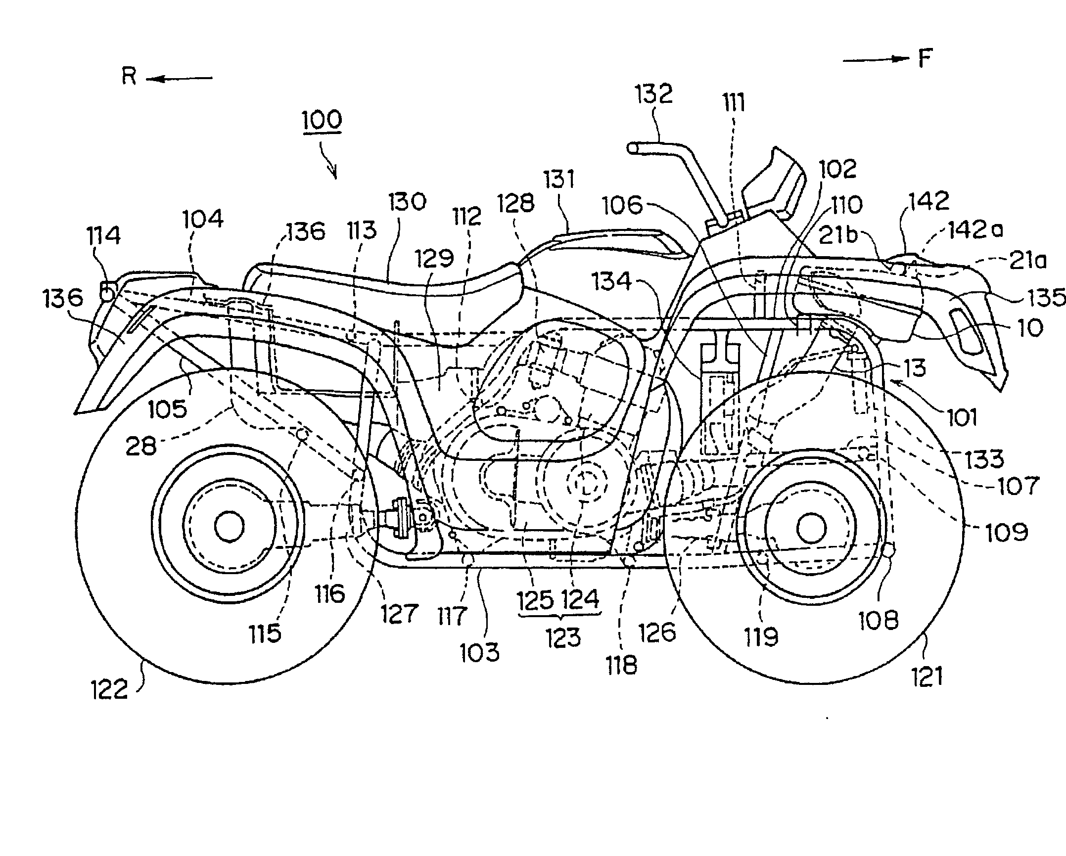
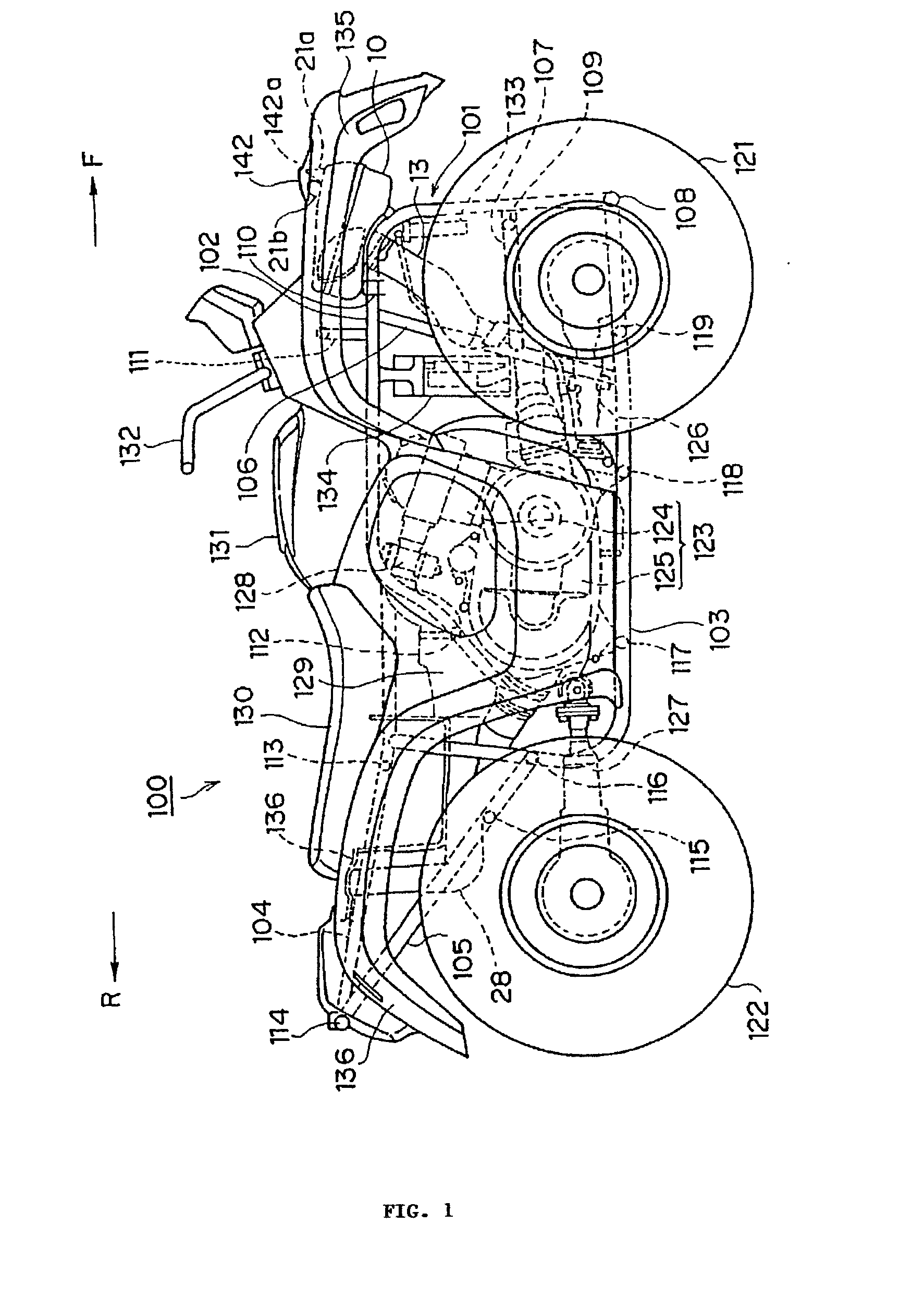
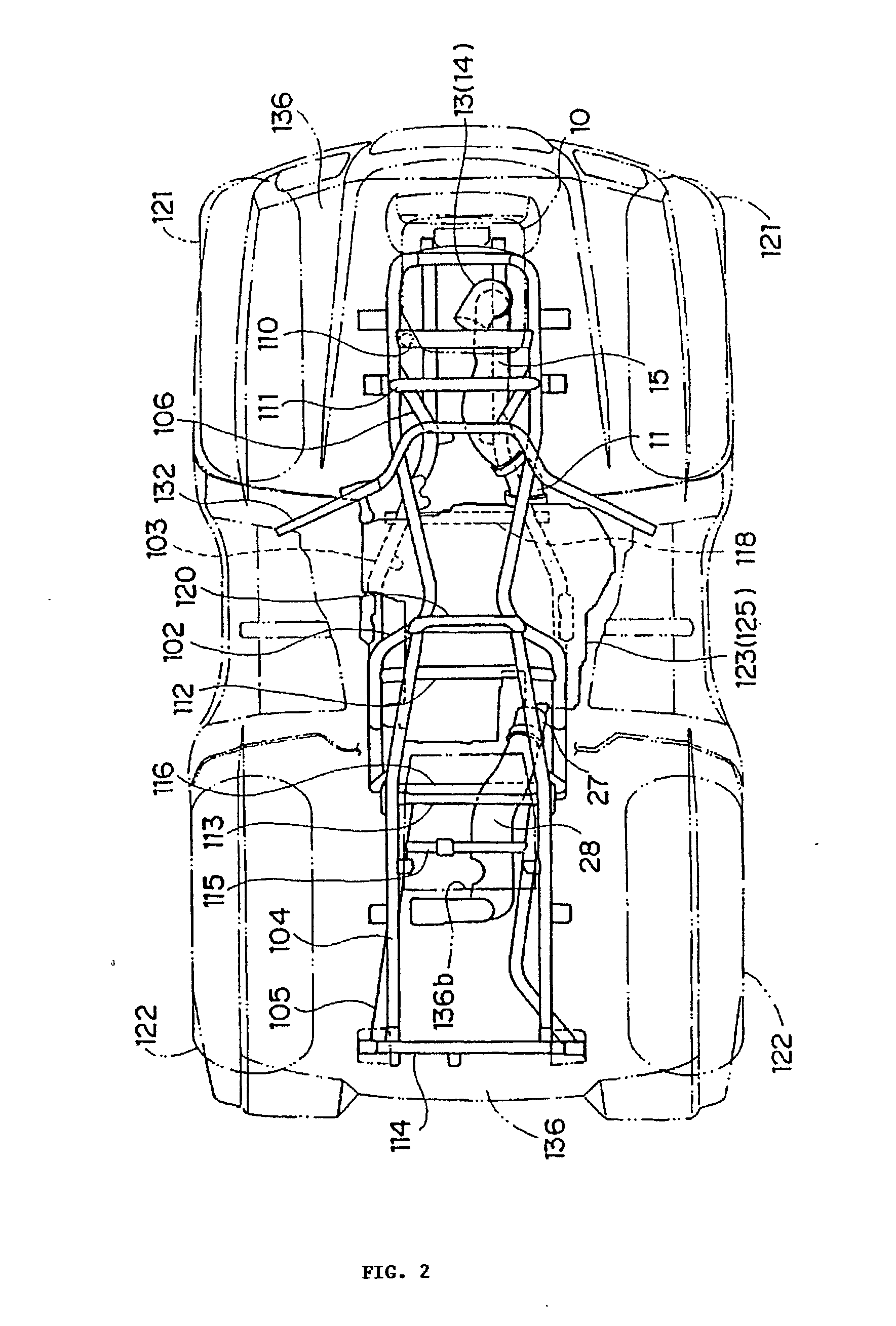
[0002] The present invention relates to a transmission cooling system for a saddle-type vehicle such as an all-terrain vehicle.
[0003] 2. Background of the Invention
[0004] All-terrain vehicles have outstanding performance on pavement and also demonstrate high maneuverability under severe conditions including off-road and marshy conditions. The basic structure of this type of vehicle comprises a frame fitted with four wheels, an engine mounted thereupon, and a seat as well as a fuel tank located above. When a belt, instead of a chain, is used as the mechanism for transmitting engine output to the wheels, the temperature within the belt case rises due to friction heat, and that heat reduces the belt's durability. Thus, moving air is actively taken into the belt case to cool the belt while the vehicle is underway and it is discharged from the belt case after cooling the belt.
[0005] For example, in the cooling system of a belt-type transmission stated in t...
PUM
 Abstract
Description
Claims
Application Information