Subsurface engraving of three-dimensional sculpture

a three-dimensional sculpture and surface engraving technology, applied in the field of sculpture creation, can solve the problems of too close proximity of spots/dots/cracks/destructions, cracking/destruction at the concentration point of laser beams, and sculpture value loss

Inactive Publication Date: 2003-04-10
TREX ENTERPRISES CORP
View PDF0 Cites 5 Cited by
  • Summary
  • Abstract
  • Description
  • Claims
  • Application Information

AI Technical Summary

Benefits of technology

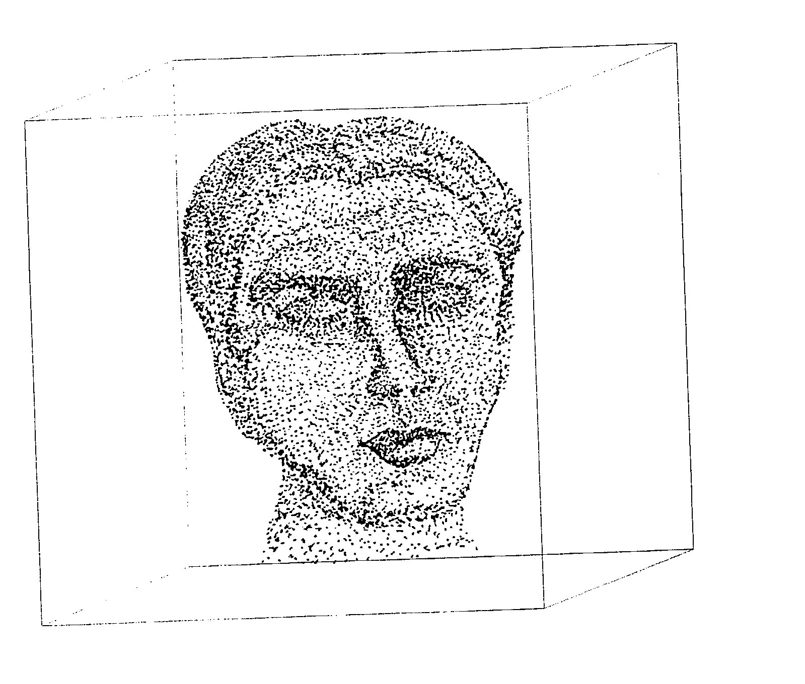
[0011] Thus, there is a wide range of control of the internal sculpture that is produced. Additionally, sculpting can be performed on the external surfaces of the matrix as well as close to these external surfaces without cracking / destruction. Spacing between dots and lines allow for the production of a three-dimensional-translucent, see-through sculpture, floating ghost-like in a clear matrix. The matrix material may be colorless or tinted so long as it remains sufficiently clear to permit the laser beam penetration from its external position.
[0013] Because the sculpting is performed on a matrix in a semi-solid, that is, somewhat gelatinous state, there is no cracking of the matrix material, and a finer detailing of the finished sculpture is possible.

Problems solved by technology

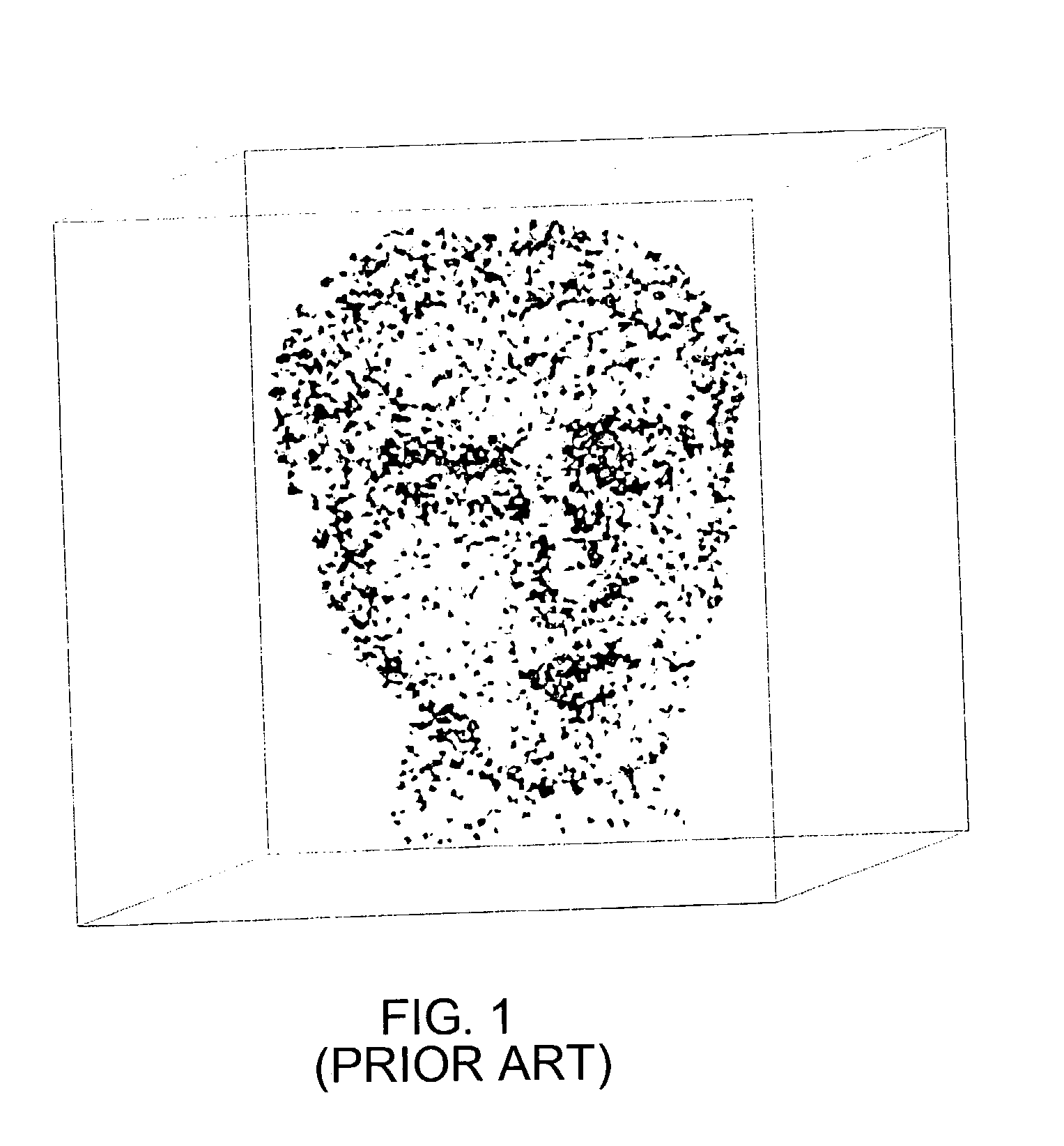
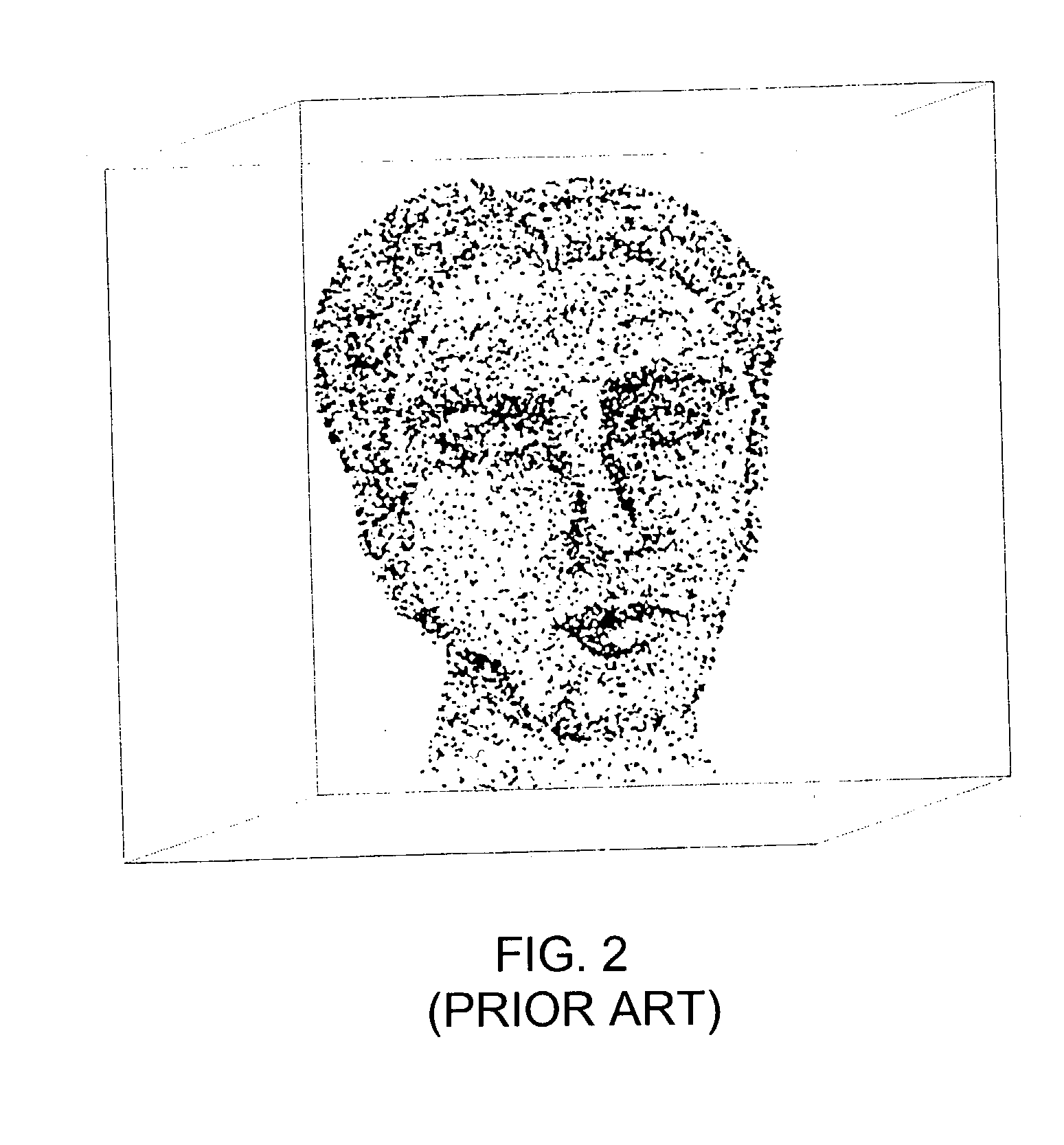
Clearly in the prior art, there is a degree of cracking / destruction at the point of concentration of the laser beam.
However, a problem arises when the laser spots / dots / cracks / destruct-ions, etc. are too close together or too near the external surfaces of the matrix.
Then, a defect in the internal sculpture results or subsequent changes with time may render the sculpture valueless.
This internal damaging of the material limits the closeness of the dots that are generally formed in the prior art as well as their location relative to the outer surfaces of the matrix.
The quality of the internal sculpture is adversely affected.
This is not possible in the prior art where the material is cracked / destroyed, as the thermal energy is applied to a solid.

Method used


Image

  • Subsurface engraving of three-dimensional sculpture
  • Subsurface engraving of three-dimensional sculpture
  • Subsurface engraving of three-dimensional sculpture

Examples


Embodiment Construction

[0027] FIG. 4, taken from Pat. No. 5,575,936, mentioned above and incorporated herein by reference, illustrates a basic method of subsurface engraving in a solid transparent matrix. Fractures are produced in the matrix 15 by a laser beam 12 that is focused within the matrix 15 by a lens 13. The solid matrix 15 is positioned on a movable platform 16 which is moved under direction of the controller 17. Thus the laser 11 can produce a plurality of destructions / disruptions at the focal point 14 which is moved within the matrix 15 from dot to dot.

[0028] Refinements in this procedure are added in the other patents mentioned above, which are also incorporated herein by reference. The laser may be pulsed or operate steady state while the focal point location is changed to produce a plurality of dots. Procedures for operation of the laser apparatus itself and its control are not a novel portion of the present invention and accordingly, are not discussed in detail herein.

[0029] In the present...


PUM

PropertyMeasurementUnit
transparentaaaaaaaaaa
temperatureaaaaaaaaaa
physical gelaaaaaaaaaa

Abstract

A matrix is formed into a desired shape by pouring transparent liquid material into a mold. The material progresses from the liquid to the gelatinous state. Laser sculpting steps are performed when the material is still in a gelatinous condition to form small spots in the matrix. Because the material is non-solid gel when the laser beam applies its focused energy, there is no cracking or destruction. Intensity and duration of the laser pulse determine the size of the spots as does the timing in relation to the matrix material finally changing from gel to solid. Particular visual effects are produced at different degrees of solidity when sculpting. The liquid in the mold may be pressurized for removal of air bubbles after initial pouring of the matrix material and application of pressure after the laser sculpting controls the size of the spots in the finished product.

Description

[0001] This is a division of U.S. application Ser. No. 09 / 645,124 filed Aug. 24, 2000, now pending.BACKGROUND OF THE INVENTION:[0002] This invention relates to the creation of a sculpture generated by a laser beam directed at a transparent matrix, and more particularly, to a sculpture engraved within the surfaces of a transparent matrix.[0003] There are many souvenirs and art objects wherein a translucent ghost-like image in two or three dimensions is seen floating within a solid piece of clear plastic or glass.[0004] In recent years these translucent objects have been produced internally using a programmed laser that is brought to focus sequentially at many locations within the transparent matrix. The energy concentrated at the point of focus changes the matrix material so that the translucent three-dimensional object is created of many spots within the transparent plastic or glass matrix.[0005] XYZ axis programming in positioning the matrix relative to the laser source provides en...

Claims


Application Information

Patent Timeline
Patent Type & Authority Applications(United States)
IPC IPC(8): B29C35/08B29C39/02B44B1/00B44B7/00B44C3/06
CPCB29C39/026B29C2035/0838B29C2791/009Y10T428/24364B44B1/00B44B7/00B44C3/06B29L2031/722
Inventor COLEA, OVIDIU
Owner TREX ENTERPRISES CORP
Why Eureka
Try Eureka