Water closet flushing system

a technology for flushing systems and water closets, applied in the direction of valve operating means/releasing devices, functional valve types, transportation and packaging, etc., can solve the problems of ineffective attempts to adjust, the pressure of the water supply is often too high for the water closet system to function properly, and the inability to accept the high pressure of the water supply used to operate the flush valv

Inactive Publication Date: 2003-04-24
PINO WILTON J
View PDF0 Cites 9 Cited by
  • Summary
  • Abstract
  • Description
  • Claims
  • Application Information

AI Technical Summary

Benefits of technology

0008] Another object of this invention is to provide an improved water closet system that is easy to adjust without significant training by the plumber.
0009] Still another object of this invention is to provide an inexpensive means to control the water pressure in a diaphragm flush valve during the flushing cycle.

Problems solved by technology

One reoccurring problem with the use of a diaphragm flush valve has been the unacceptable high pressure of the water supply used to operate the flush valve.
Unfortunately, the pressure of the water supply is often too high for the water closet system to properly function.
These attempts have not been as effective as would be desired.
If the water pressure is set too low, then the valve does not get enough water to consistently function properly.
A second problem has been in training personnel to correctly adjust the water pressure at the inlet opening of the valve inlet chamber.

Method used


Image

  • Water closet flushing system
  • Water closet flushing system
  • Water closet flushing system

Examples


Embodiment Construction

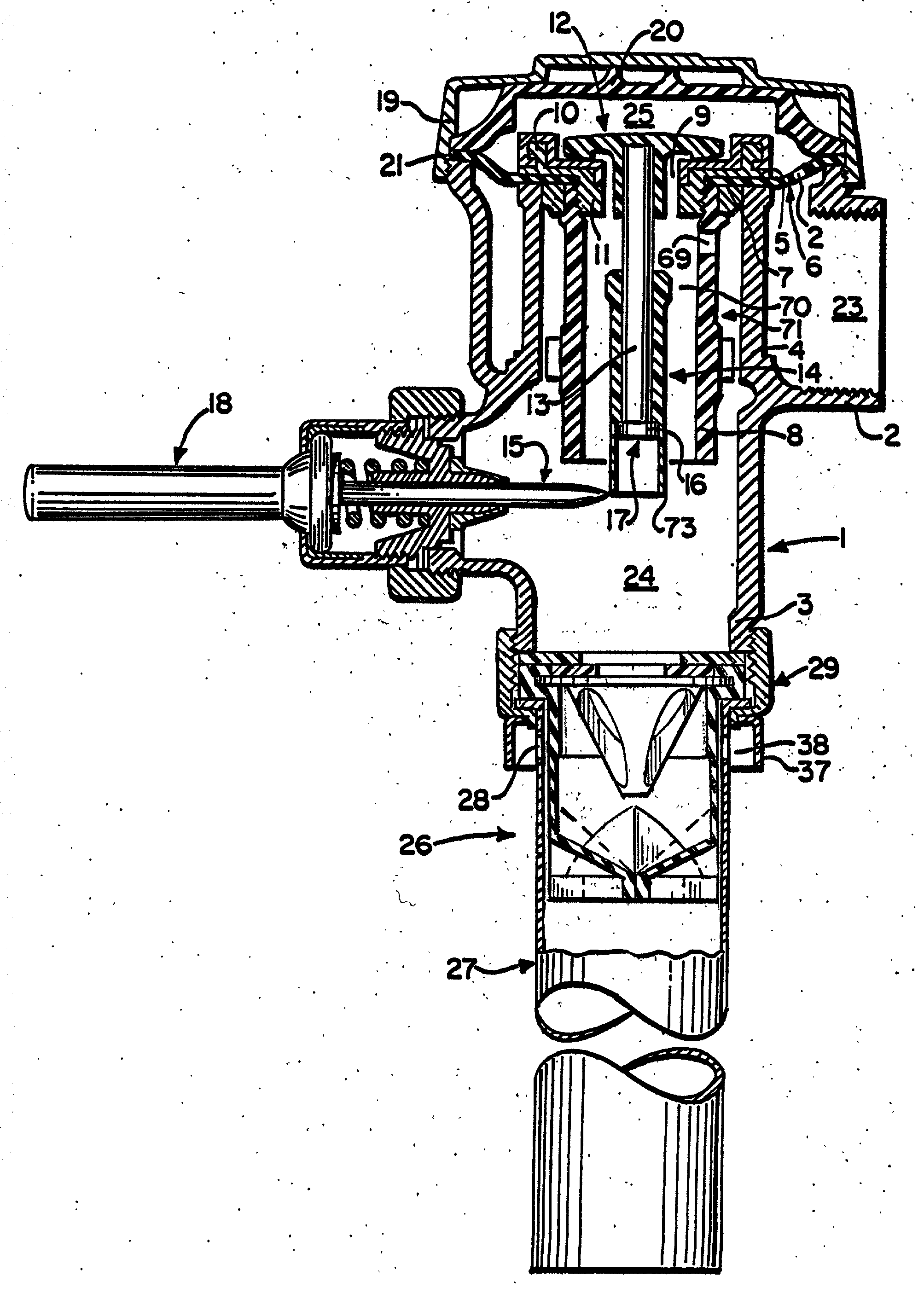
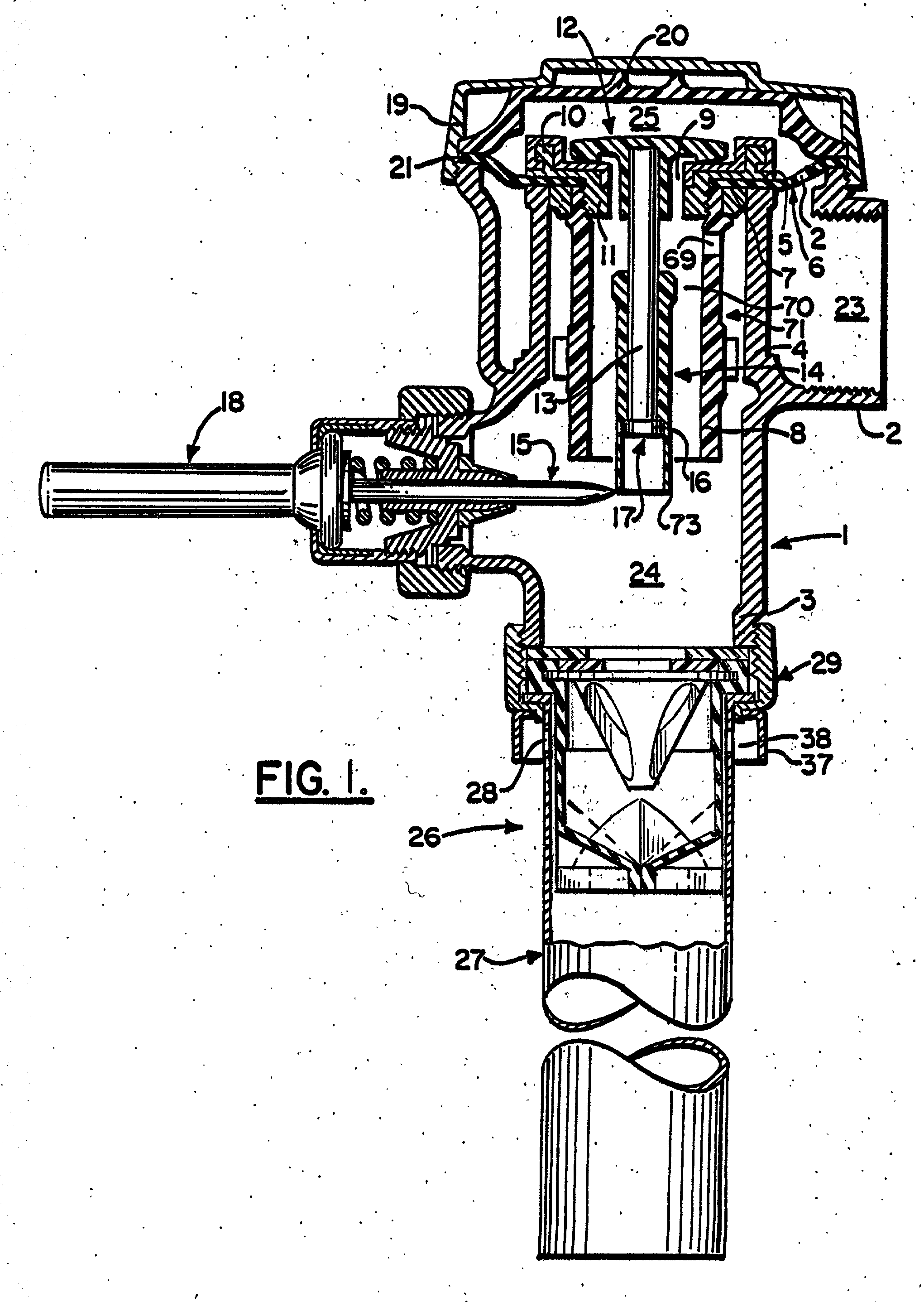
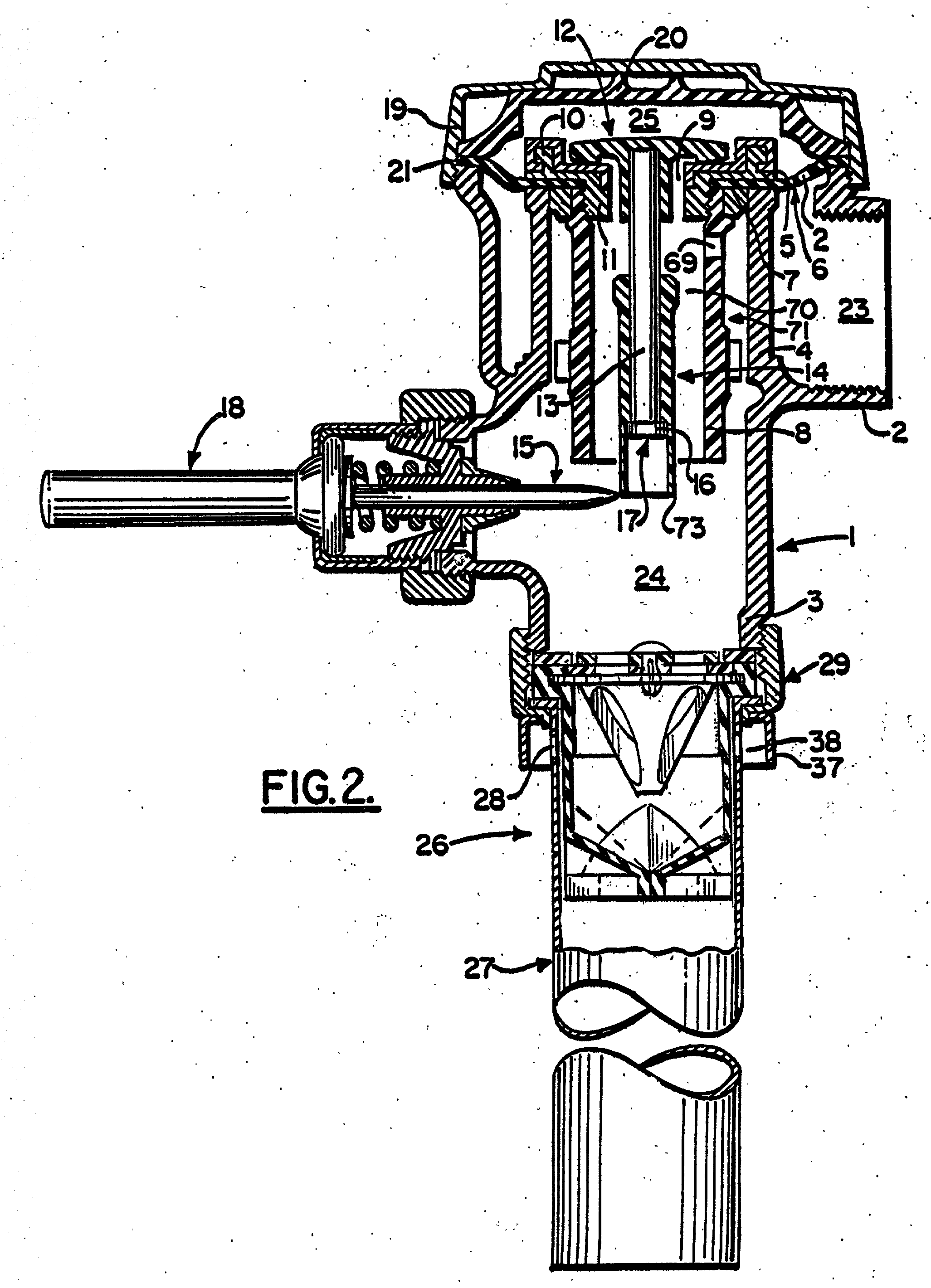
[0025] As used in this patent, the term "diaphragm flush valve" refers to a flush valve having a fluid inlet chamber, an upper chamber and an outlet chamber, wherein the chambers are separated from one another by a flexible diaphragm provided with a by-pass opening connecting the fluid inlet chamber to the upper chamber and with a central opening connecting the upper and outlet chambers, which central opening is sealable by a relief valve assembly comprising a relief valve having a vertically disposed stem about which a sleeve member can freely slide a predetermined distance, and a plunger assembly having a flush initiating means which when engaged causes a plunger pin to operatively contact the sleeve member unseating the sealing member and permitting flow of fluid from the upper chamber to the lower chamber. Without any intent to restrict the definition of diaphragm flush valves, examples of such are described in U.S. Pat. Nos. 1,714,573, 2,776,812, 3,399,860, 3,556,137, 3,656,499...


PUM


Abstract

An improved water closet flushing system utilizing a diaphragm flush valve having a fluid flow control means positioned to receive the fluid discharged from the diaphragm flush valve prior to fluid entering the water closet bowl.

Description

[0001] 1. Field of the Invention[0002] This invention relates in general to water closet systems, and more particularly, to an improved means to control during the flushing cycle the pressure differential between the inlet and outlet chambers of a diaphragm flush valve used in the water closet system.[0003] 2. Prior Art[0004] Flush valves, and in particular flush valves used in the construction of water closets or urinals, have been used for many years. See, for example, U.S. Pat. No. 30,462 issued Oct. 23, 1860. However, the forerunner to one of the most popular modern diaphragm flush valve designs is disclosed in U.S. Pat. No. 1,714,573 issued May 28, 1929, and commonly referred to as a diaphragm flush valve. A modern version of the diaphragm flush valve is disclosed in U.S. Pat. No. 6,227,219 entitled "Flush Relief Valve Having Improved Vacuum Breaker" and issued on May 8, 2001 by the inventor herein.[0005] One reoccurring problem with the use of a diaphragm flush valve has been ...

Claims


Application Information

Patent Timeline
Patent Type & Authority Applications(United States)
IPC IPC(8): E03D3/06F16K15/14F16K31/385G05D16/04
CPCE03D3/06G05D16/04F16K31/3855F16K15/147Y10T137/3331Y10T137/7897
Inventor PINO, WILTON J.
Owner PINO WILTON J
Why Eureka
Try Eureka