
Aiding beam identification in a satellite system

a satellite system and beam identification technology, applied in the field of satellite communications and satellite communications systems, can solve the problems of affecting the accuracy of satellite measurements, the complexity of the travel process of mobile phones, and the increase in the demand for associated communications systems

Active Publication Date: 2003-05-22
QUALCOMM INC
View PDF8 Cites 22 Cited by
  • Summary
  • Abstract
  • Description
  • Claims
  • Application Information

AI Technical Summary

Benefits of technology

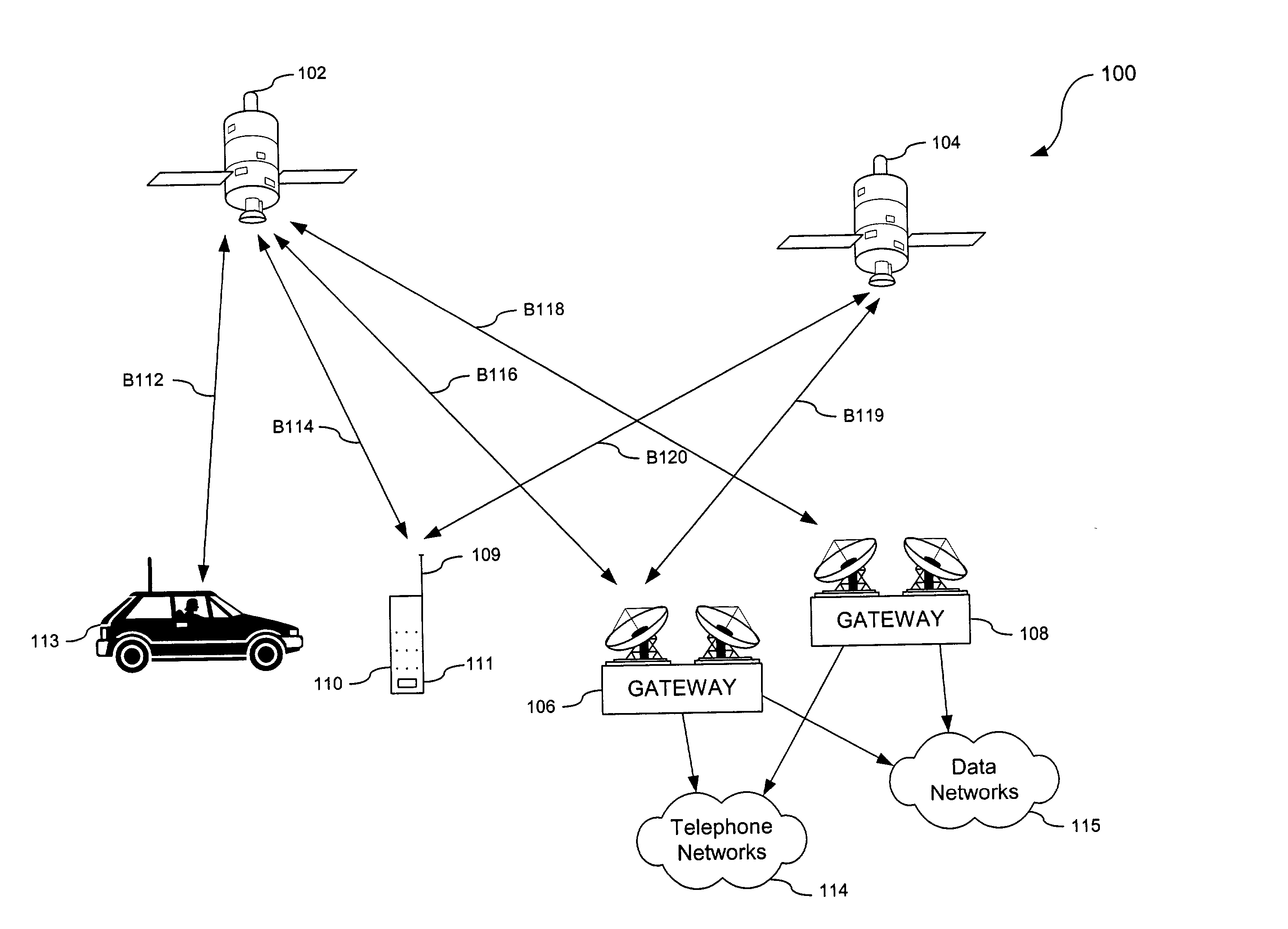
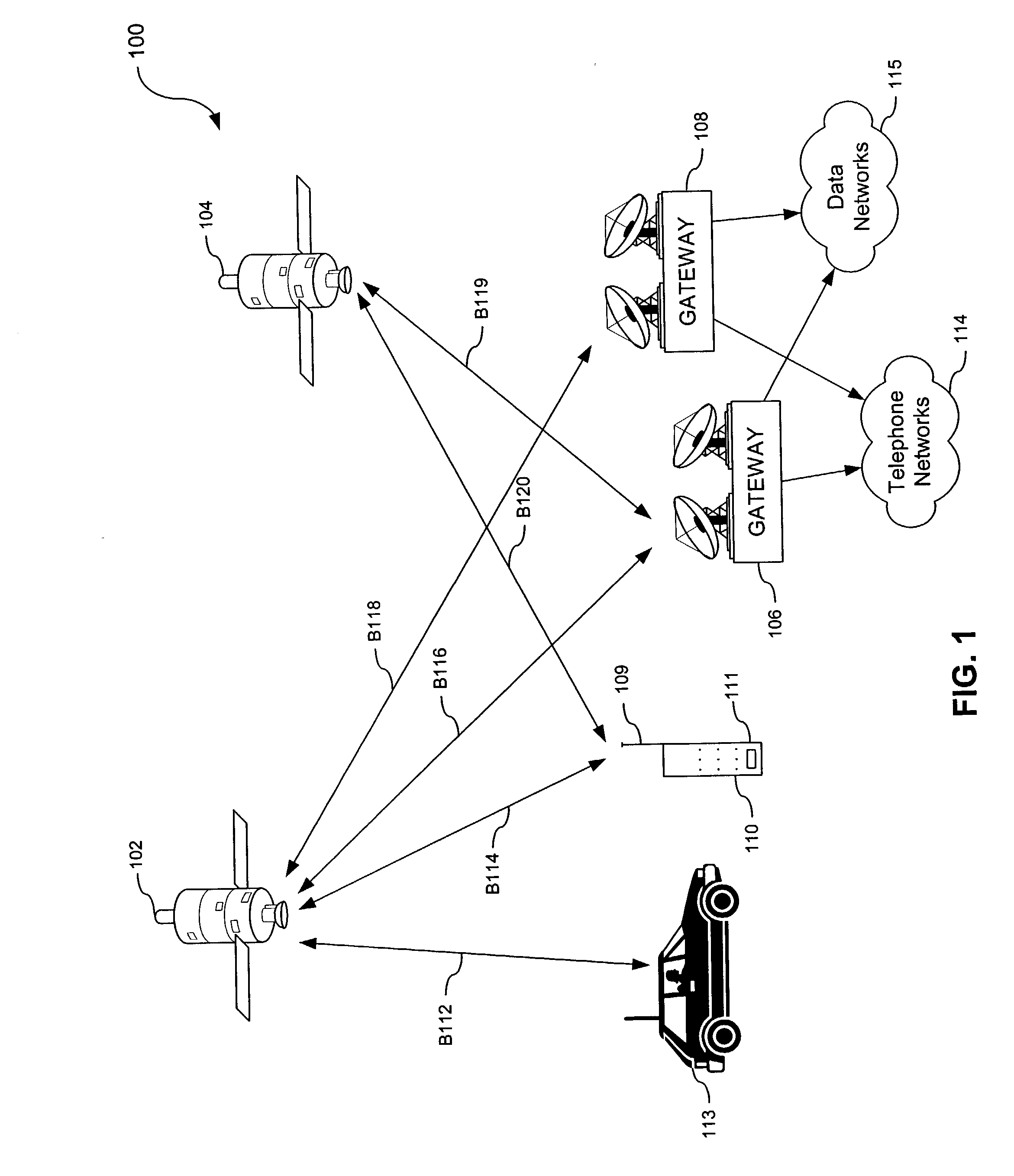
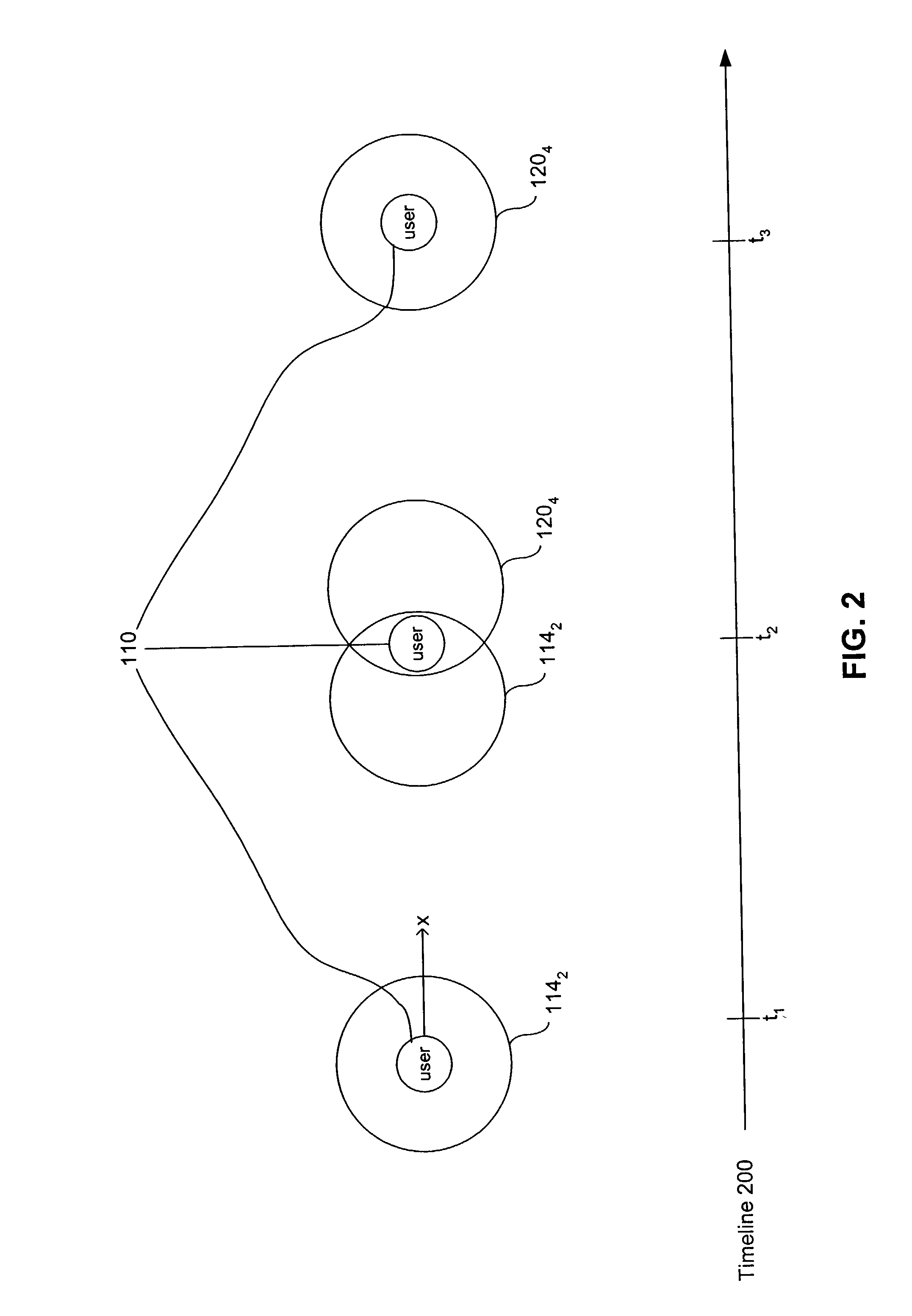
[0024] A method is also provided to perform beam identification in a user terminal configured to communicate using a low earth orbit satellite system, the user terminal including a processor configured to receive a first satellite beam including a first timing offset from a servicing satellite, and facilitate a handoff from the first satellite beam to a second satellite beam, the second satellite beam being radiated from a destination satellite. The method comprises acquiring the second satellite beam in the user terminal, determining a second timing offset of the second satellite beam based upon the first timing offset; identifying the second satellite beam based upon the second timing offset estimating a first range from the user terminal to the servicing satellite; estimating a second range from the user terminal to the destination satellite; determining a timing difference based upon a difference between the estimated first range and the estimated second range; calculating a difference between the second timing offset and the timing difference; and confirming identification of the second satellite beam when the difference between the second timing offset and the timing difference is greater than a predetermined value.
[0027] Features and advantages of the present invention include an ability to independently verify the user terminal's PN offset or beam ID measurement. This ability enhances the accuracy of identifying satellite beams, thus increasing the certainty of a user terminal gaining access to the communication system. Unknown propagation delays, which may result from low-horizon satellites and PN offset errors resulting therefrom, may be determined and compensated for. Therefore, the accuracy with which user terminals determine the satellite beam ID of destination satellite beams may be increased. Correspondingly, users may use the satellite communications system with increased assurance that the required system services will not be interrupted or altogether denied.

Problems solved by technology

Although mobile phones or wireless user terminals provide users with increased mobility and flexibility, the proliferation of such phones have increased the demands on the associated communications systems.
However, the flexibility of travel for mobile phones complicates this process.
However, although motion between satellites and associated user terminals can be determined, errors often occur in these measurements due to effects such as antenna gain characteristics or, for example, because a particular satellite may be low in elevation with respect to the user terminal.
These errors often result in the gateway misidentifying the servicing or communicating satellite's beam and consequently mis-judging the position of the user terminal.
The end result of misidentification of the satellite's beam is often denial of system services, or even complete radio link acquisition failure for the associated user.
Another source of errors may arise as part of the implementation of specific communication techniques or user access methods employed by communication systems to accommodate multiple system users.
Although CDMA is spectrally efficient, CDMA systems are also somewhat vulnerable to problems associated with the mobile station or terminal mis-positioning errors discussed above.
One area where CDMA systems are particularly vulnerable is the area of user handoffs.
The amount of propagation delay between communication system satellites and the user terminal is often significant and uncertain, and may cause unknown shifts in PN offset values being detected.
These shifts may result in the user terminal misidentifying a new hand-off or destination satellite beam.
Unknown propagation delays are especially probable when the new destination satellite is low on the horizon with respect to the current servicing satellite in the cited references.

Method used


Image

  • Aiding beam identification in a satellite system
  • Aiding beam identification in a satellite system
  • Aiding beam identification in a satellite system

Examples


Embodiment Construction

[0041] The following detailed description of the present invention refers to the accompanying drawings that illustrate exemplary embodiments consistent with this invention. Other embodiments are possible, and modifications may be made to the embodiments from the spirit and scope of the invention. Therefore, the following detailed description is not meant to limit the invention. Rather, the scope of the invention is defined by the appended claims.

[0042] It would be apparent to one of skill in the art that the present invention, as described below, may be implemented in many different embodiments of hardware, software, firmware, and / or the entities illustrated in the figures. Any actual software code with specialized controlled hardware to implement the embodiments is not limiting of the present invention. Thus, the operation and behavior of the present invention will be described with the understanding that modifications and variations of the embodiments are possible, given the level...


PUM


Abstract

A system and method for determining timing offset errors in a low earth orbit satellite system based upon Doppler and Doppler rate of change is provided. A user terminal determines first and second timing offsets respectively associated with first and second satellite beams from respective first and second satellites. Next, the user terminal determines the Doppler and Doppler rate of change associated with the first and second satellite beams. A timing offset is estimated from the measured Doppler and Doppler rate of change and is then compared with the user terminal's own determined timing offset. If the comparison does not produce a value within a predetermined threshold, a beam identification error is declared.

Description

[0001] This application claims priority from U.S. Provisional Patent Application entitled "Method and System for Aiding Beam Identification In A LEO Satellite System," Serial No. 60 / 342,925, filed Oct. 25, 2001, which application is incorporated herein by reference in its entirety.[0002] I. Field of the Invention[0003] The present invention relates generally to satellite communications and satellite communications systems. More particularly, the present invention relates to estimating and compensating for propagation delays associated with identifying satellite beams in a satellite communications network.[0004] II. Background Art[0005] Conventional satellite communications systems include one or more terrestrial base stations (hereinafter referred to as gateways), user terminals, such as a mobile phone, and one or more satellites for relaying communications signals between the user terminal and the gateway. The gateway receives signals from and transmits signals to satellites, which...

Claims


Application Information

Patent Timeline
Patent Type & Authority Applications(United States)
IPC IPC(8): H04B7/185H04B1/00
CPCH04B7/1855
Inventor ANDERSON, JON J.DAI, JINNGAI, FRANCIS M.VICTOR, EDWARD B.
Owner QUALCOMM INC
Learn More