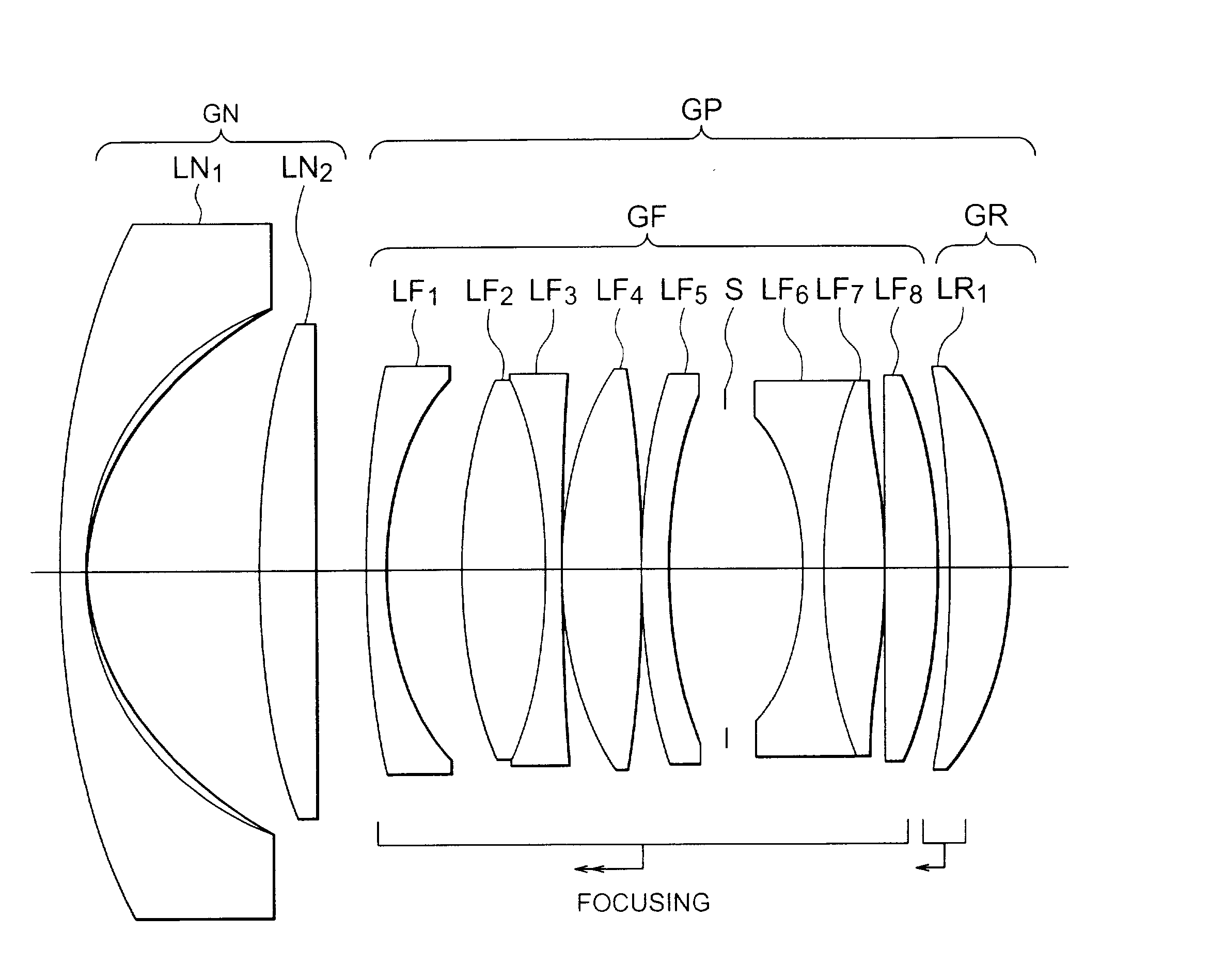
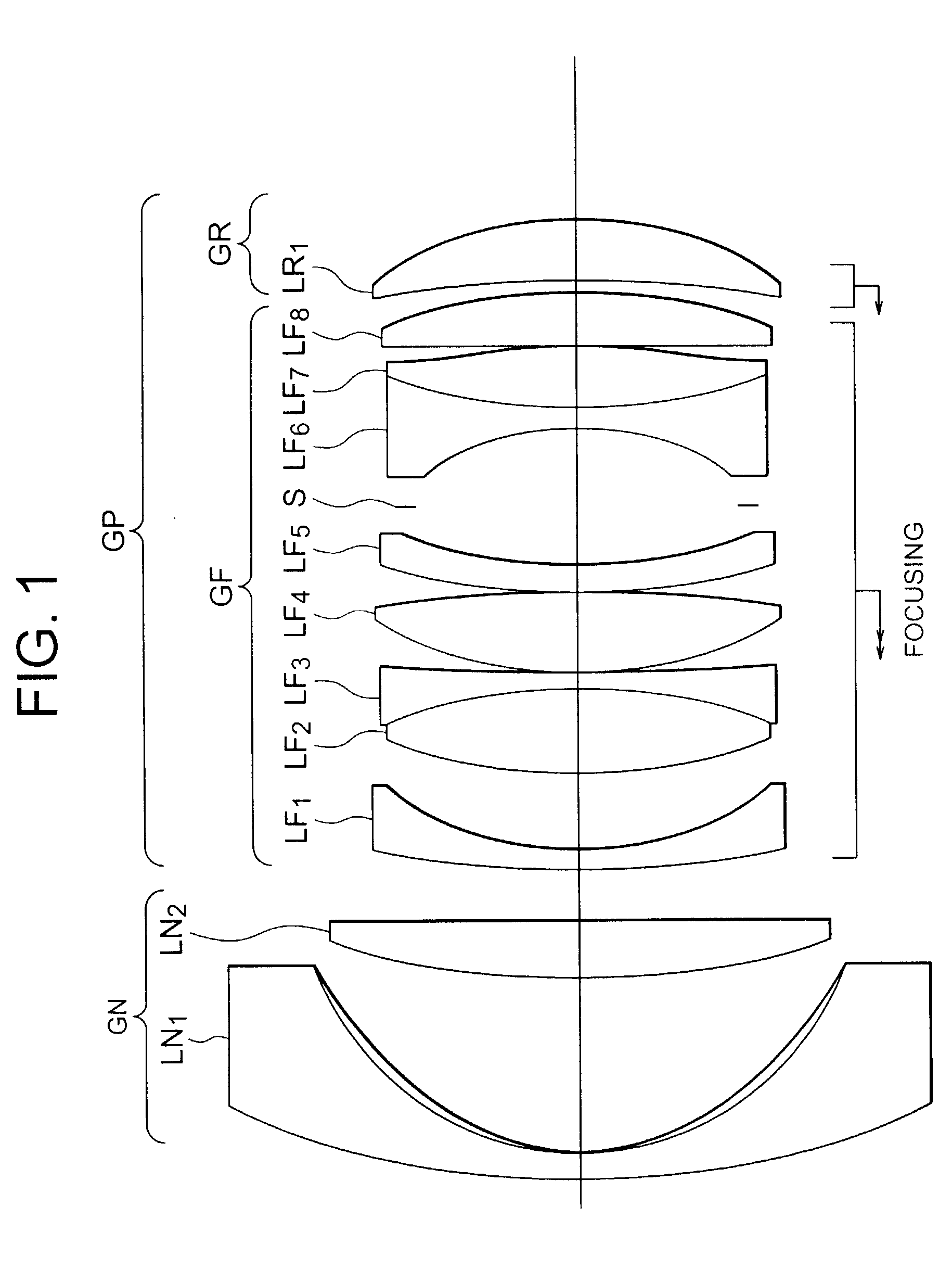
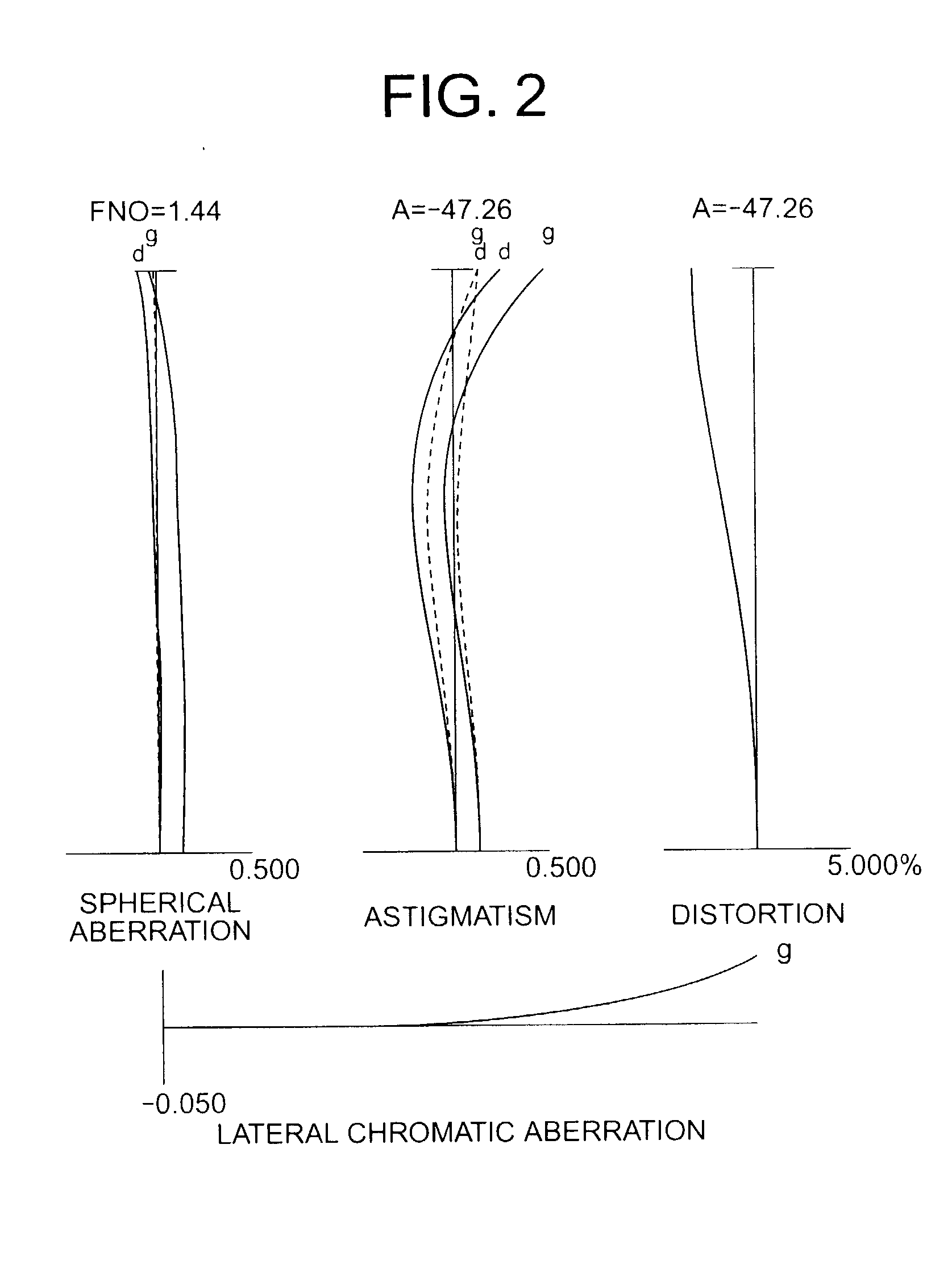
In order to develop a large aperture, super wide-angle lens system, there are technical problems such as compactness for general use, high optical performance, securing a
peripheral quantity of light, using an aspherical surface having
high productivity, and, in particular, controlling variation in aberrations upon focusing at a close or short distant object relative to aberrations upon focusing at an object at infinity, of a super
wide angle lens system having extremely large angle of view.
Difficulty in correcting close-range aberration variation in addition to difficulty in improving optical performance upon focusing at infinity makes it further difficult to accomplish a lens system having the specifications.
In addition, if you try to make the lens system to have a wider angle of view, the lens system becomes further larger.
Moreover, correction of
astigmatism and
coma is not sufficient, so variation in aberrations upon focusing is not small sufficiently.
Furthermore, since the lens system carries out focusing by moving inner lens group of a retrofocus type lens system, the lens system unavoidably becomes large in order to secure
dead space.
On the other hand, no matter how expands the lens designing technique, a lens design having high optical performance and compactness cannot be derived from the lens system disclosed in Japanese
Patent Application Laid-Open No. 7-35974.
In the optical design of an objective lens system including a photographic lens system, the most difficult problem is to satisfy both a large angle of view and a large aperture at the same time.
However, in order to widen the angle of view in the conventional construction, since the wide converter portion is allotted heavy power distribution, it is impossible for the conventional construction to reach a design solution with high optical performance.
As described above, it is the main technical problem for a lens system having extremely large angle of view to control close-range aberration variation.
Moreover, if the aperture is extremely large, acceptable amounts of remnant aberrations become exceptionally small.
Accordingly, the difficulty in correcting close-range aberration variation in addition to the difficulty in improving optical performance upon focusing at infinity makes it further difficult to accomplish a lens system having the said specifications.
The above-described aberrations move in
positive direction upon focusing close object, resulting in degradation of optical performance.
This is disagreeable.
On the other hand, when the ratio falls below the
lower limit of
conditional expression (1), the moving amount of the rear lens group GR becomes too small in comparison with that of the front lens group GF, so that close-range aberration correction cannot be carried out properly.
The above-described aberrations move in negative direction upon focusing close object, resulting in degradation of optical performance.
This is disagreeable.
At last, the appropriate range of
conditional expression (1) is no longer satisfied, so that it is undesirable.
On the other hand, when the ratio falls below the
lower limit of
conditional expression (2), the refractive power of the rear lens group GR becomes excessively strong in comparison with that of front lens group GF.
At last, the appropriate range of conditional expression (1) is no longer satisfied, so that it is undesirable.
When the
focal length ratio exceeds the upper limit of conditional expression (3), it means that the refractive power of the positive lens group GP becomes excessively strong in comparison with that of the negative lens group GN, or the refractive power of the negative lens group GN becomes excessively weak in comparison with that of the positive lens group GP.
Consequently, various aberrations become worse and the speed (aperture) of the lens system cannot be secured, so that it is undesirable.
In the latter case, the negative lens group GN becomes large and the whole lens system becomes large, so that it is undesirable.
On the other hand, when the ratio falls below the
lower limit of conditional expression (3), it means that the refractive power of the positive lens group GP becomes excessively weak in comparison with that of the negative lens group GN or the refractive power of the negative lens group GN becomes excessively strong in comparison with that of the positive lens group GP.
Accordingly, the burden of correction of off-axis aberration imposed on the negative lens group GN becomes heavy, so that correction of off-axis aberration becomes worse.
In the latter case, correction of off-axis aberration becomes worse, the number of lens elements increases, the thickness of each lens element increases, and the
diameter of the front lens group becomes large, so that it is undesirable.
Although the shape is preferable for correcting aberrations, drastic change in shape is not good for correcting aberrations or may reach a design solution which is actually unable to manufacture, so that it is undesirable.
Accordingly, it tends to introduce a drop in
peripheral quantity of light and an increase in
diameter of front lens group, so that it is not desirable.
As a result, inclination (differential) of
spherical aberration becomes large and a so-called "undulation" becomes conspicuous, so that optical performance lowers.
Moreover, various aberrations such as
coma, and
distortion become over-corrected to be even worse.
Accordingly, accuracy in
processing lowers, so that it is undesirable.
On the other hand, when the ratio falls below the lower limit of conditional expression (6), the effect of designed aspherical surface diminishes, so that sufficient aberration correction becomes impossible.
So, it is undesirable.


