Routing traffic in a communications network

a technology for routing traffic and communications networks, applied in data switching networks, digital transmission, data switching by path configuration, etc., can solve problems such as negating some benefits and adding to the complexity of the system

Inactive Publication Date: 2003-06-26
RPX CLEARINGHOUSE
View PDF6 Cites 62 Cited by
  • Summary
  • Abstract
  • Description
  • Claims
  • Application Information

AI Technical Summary

Benefits of technology

0021] FIG. 1, which has been discussed above, shows in schematic form a conventional network arrangement;

Problems solved by technology

This adds to the complexity of the system and negates some of the benefits that have been provided by the introduction of MPLS.
This however, leads to statically provisioned paths between autonomous systems and does not address the problem of determining dynamic established paths e.g. to enable load balancing and to facilitate traffic engineering.

Method used


Image

  • Routing traffic in a communications network
  • Routing traffic in a communications network
  • Routing traffic in a communications network

Examples


Embodiment Construction

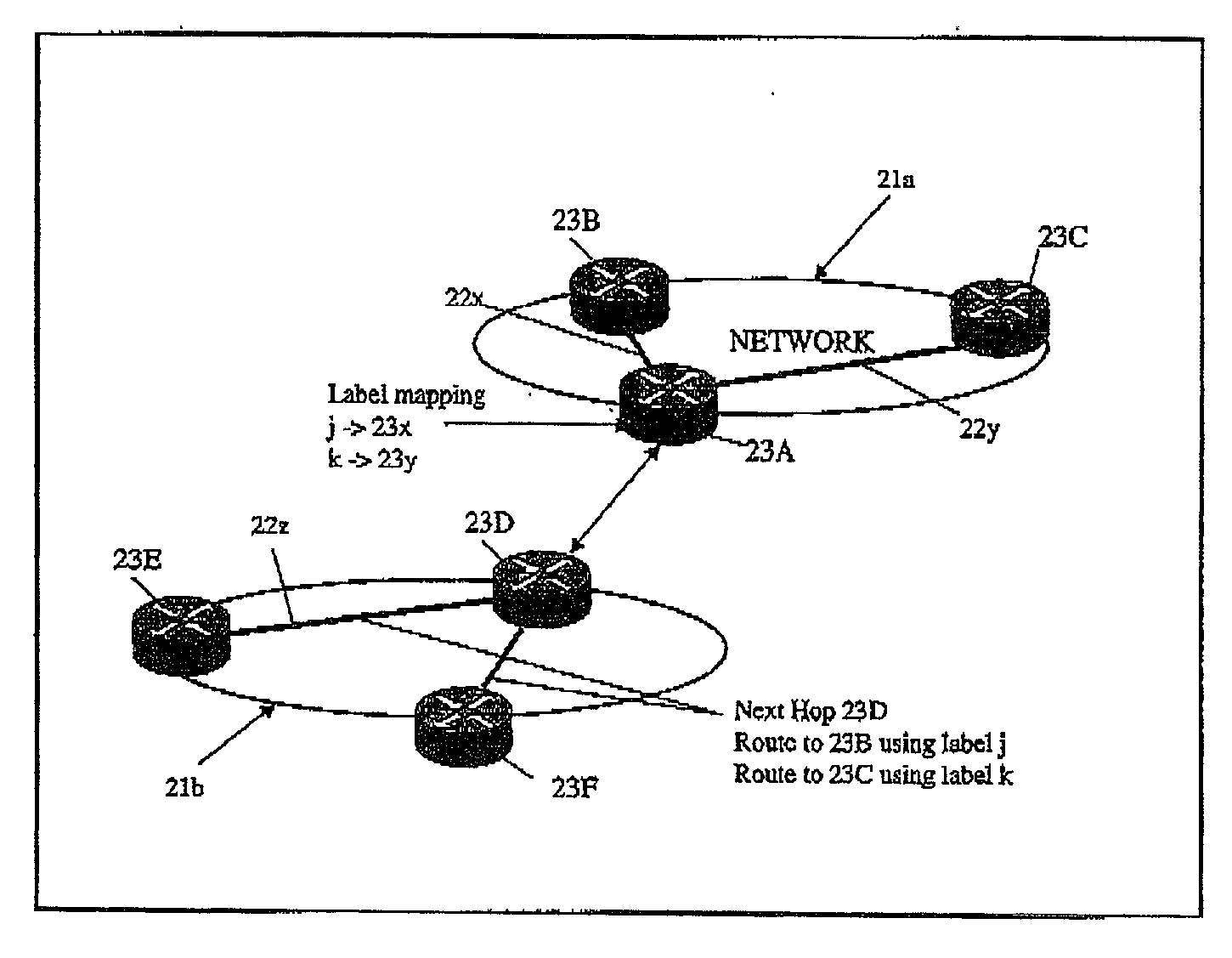
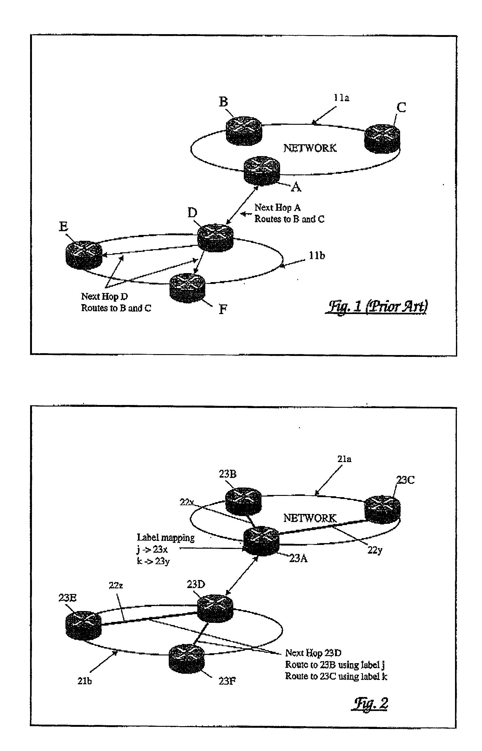
[0025] Referring now to FIG. 2, this shows a network arrangement comprising first (21a) and second (21b) autonomous systems within each of which label switched paths 22x, 22y, 22z are-established for the routing of packets within that autonomous system. It will be appreciated that for simplicity, and for the purpose of explanation, only two linked autonomous systems are shown and only a small number of routers 23A to 23C and 23D to 23F are shown in each respective autonomous system.

[0026] In the network arrangement of FIG. 2, a border gateway protocol (BGP) is employed in which a BGP label identifies both a forwarding interface for a packet and a forwarding behaviour at that interface so as to provide a mapping on to an appropriate label switched path.

[0027] BGP, as noted above, is used to notify one autonomous system of the available routes to destinations on an adjacent autonomous system. This route information is encoded in a network layer reachability information (NLRI) element ...


PUM


Abstract

In a packet communications network system, a border gateway protocol is employed to route an information packet from a source in a first autonomous system via a first label switched path to a destination in a second autonomous system via first and second border routers at an interface between the first and second autonomous systems. A label stack attached to the packet identifies both a forwarding interface for the packet and a forwarding behaviour at that interface. This provides a mapping from the first label switched path on to a second label switched path to the destination in the second autonomous system. Preferably, the destination router in the second autonomous system returns to the source router in the first autonomous system a two-label stack identifying first and second paths across the first and second autonomous systems respectively.

Description

[0001] This invention relates to apparatus and methods for the routing of packet traffic in a communications network arrangement comprising a plurality of autonomous systems.[0002] Communication networks are being developed in which traffic is carried within packets each of which is routed to an appropriate destination on the basis of information carried in a header attached to that packet. Such networks comprise a number of nodes each of which has a routing table to which reference is made to determine the processing of incoming packets. These networks include asynchronous transfer mode (ATM) and Internet Protocol (IP) networks.[0003] A development of this packet transport technique provides communication across two or more effectively independent networks, generally referred to as an autonomous system, each with its own set of nodes and routing tables. In such an arrangement, autonomous system border routers (ASBR) are provided at the boundary of each autonomous system so as to pr...

Claims


Application Information

Patent Timeline
Patent Type & Authority Applications(United States)
IPC IPC(8): H04L45/02H04L45/50
CPCH04L45/02H04L45/50H04L45/34H04L45/033
Inventor GIBSON, MARKMAUGER, ROYSTACEY, DAVE
Owner RPX CLEARINGHOUSE
Why Eureka
Try Eureka