Manifold for fuel cell system

a fuel cell and manifold technology, applied in the field of manifolds for fuel cell systems, can solve the problems of inapplicability to metal/air fuel cells, inability to achieve complex use, and undesirable variations in fluid concentration and/or flow ra

Inactive Publication Date: 2003-06-26
TECK COMINCO METALS LTD
View PDF13 Cites 26 Cited by
  • Summary
  • Abstract
  • Description
  • Claims
  • Application Information

AI Technical Summary

Problems solved by technology

However, one skilled in the art will readily recognize the geometric complexity that this technique introduces into the system after the second stage.
Such complexity is not practical for use in a metal/air fuel cell, which requires a more compact arrangement of parallel flow paths in order to integrate the manifold within a portable stacked cell design.
Multiphase fluid flow through such a manifold will typically produce undesirable variations in the fluid concentration and/or flow rate of the dispersed phase of the multiphase fluid.
The differences in pressure drops can cause differences in flow rates (e.g., veloci

Method used


Image

  • Manifold for fuel cell system
  • Manifold for fuel cell system
  • Manifold for fuel cell system

Examples


Embodiment Construction

Making of a Manifold

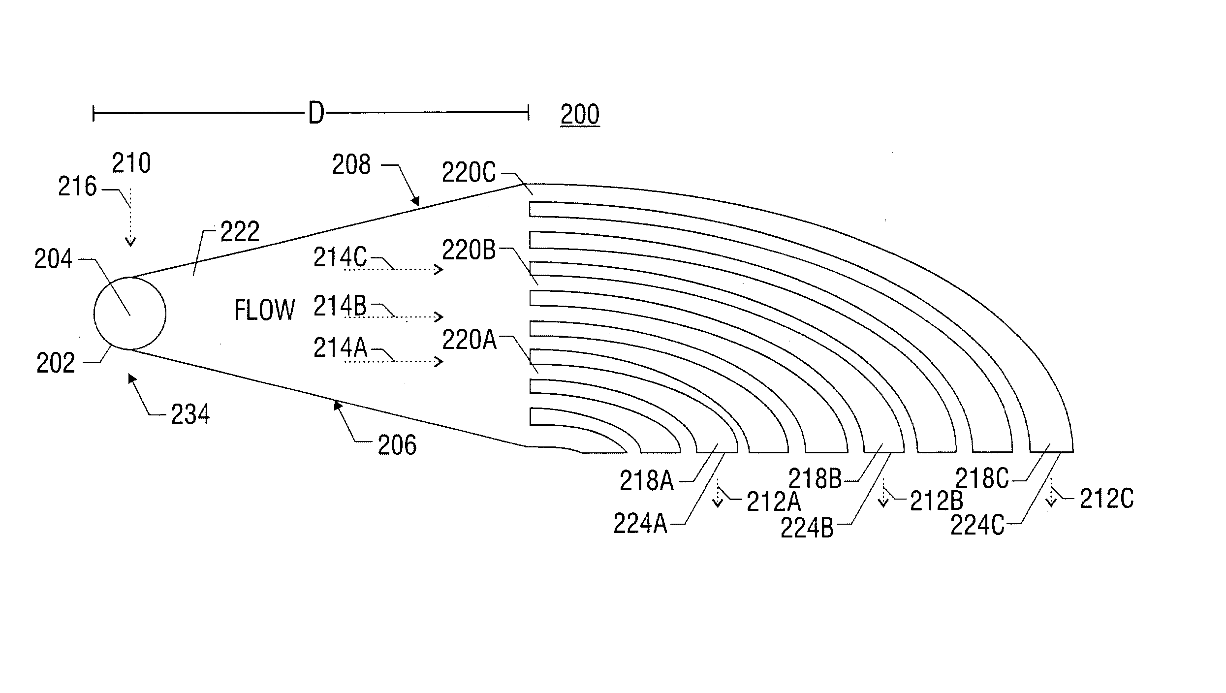
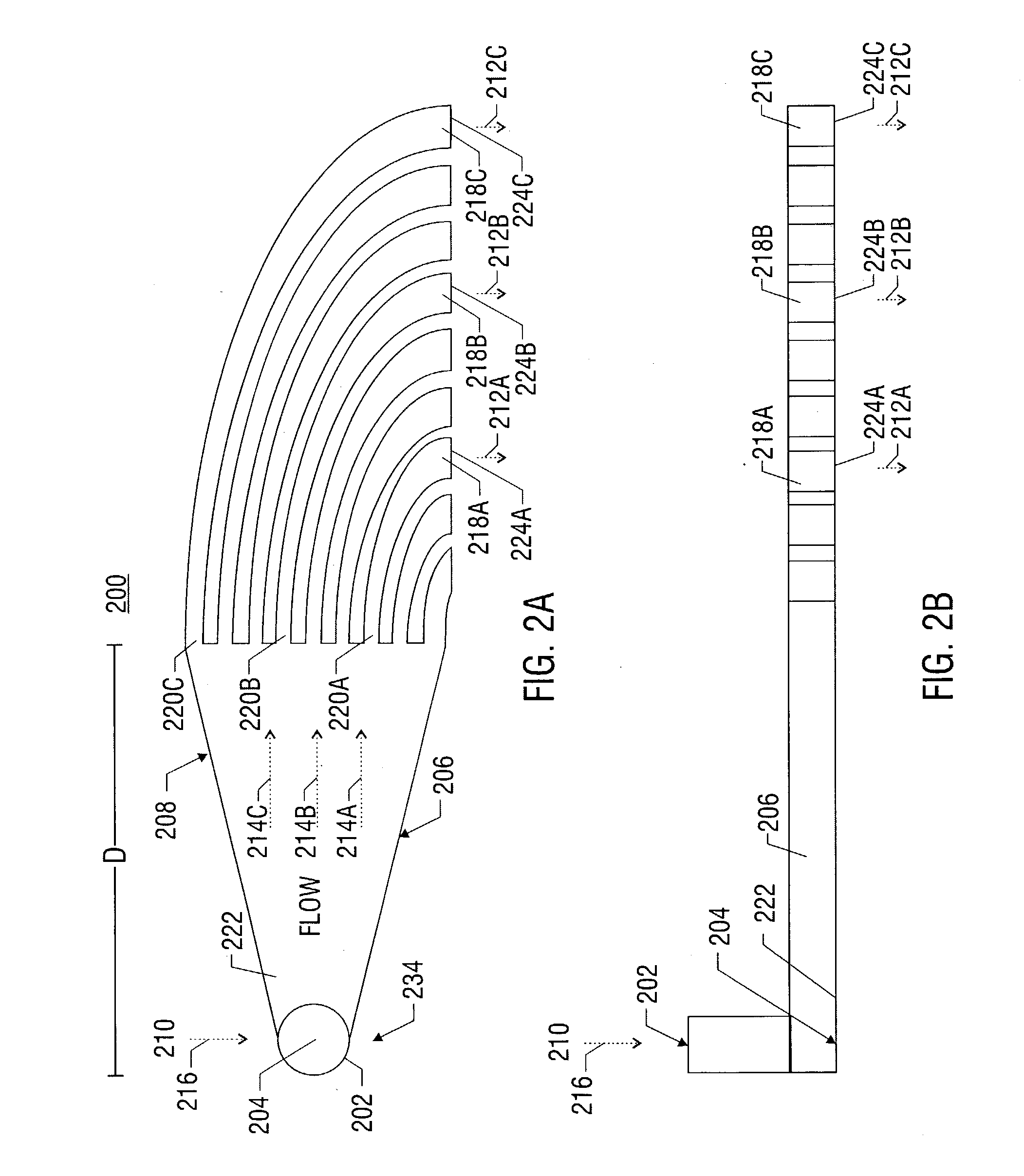
[0109] A manifold can be constructed in accordance with the invention as follows. With reference to FIG. 2a, a manifold 200 can be constructed to comprise an inlet 202 for a single flow of a multiphase fluid (e.g., solid zinc particles in a KOH liquid solution). The manifold is constructed so that the single flow impacts the base surface 204 of the inlet 202 at a 90 degree angle to the flow at a point on the base surface (e.g., the stagnation point), and can thus generate a plurality of redirected flows moving radially outward from the stagnation point and perpendicular to the original single flow. Two walls of the manifold, 206 and 208, capture only a portion of the plurality of redirected flows and further guide this portion across a predetermined distance from the stagnation point to the inlets of nine separate channels. In the case of a manifold having 9 channels, each comprising a 3 mm.times.10 mm rectangular cross section, and a 1 mm spacing between adjacen...


PUM


Abstract

A method and apparatus for converting single multiphase fluid flow into plural multiphase fluid flows having substantially uniform composition and flow properties. A manifold comprises an enclosure having an inlet and an inner surface perpendicular to the inlet such that the incident angle of input flow impacts the surface to form a stagnation point whereby an intermediate flow is deflected along the surface substantially symmetrically outward from the stagnation point and channeled to a plurality of parallel fluid outlets connected to the enclosure. The distance between the stagnation point and the plurality of outlets is selected to maintain substantially equivalent fluid pressures and uniform flow rates at the outlets. A preferred embodiment of the manifold channels the intermediate flow between two walls forming a triangular shaped nozzle directing the flow from the stagnation point to the base of the triangle for communication of electrolyte to a metal-based fuel cell through the plurality of outlets.

Description

[0001] This application is a continuation-in-part of U.S. patent application Ser. No. 10 / 072,856, filed Oct. 19, 2001, which is hereby fully incorporated by reference herein as though set forth in full.[0002] This application is related to U.S. patent application Ser. No. 09 / 930,557, entitled "POWER SYSTEM INCLUDING HEAT REMOVAL UNIT FOR PROVIDING BACKUP POWER TO ONE OR MORE LOADS," filed Aug. 15, 2001; U.S. patent application Ser. No. 09 / 930,394, entitled "METAL FUEL CELL SYSTEM FOR PROVIDING BACKUP POWER TO ONE OR MORE LOADS," filed Aug. 15, 2001; U.S. Provisional Application No. ______, entitled "ULTRA-LONG DURATION BACKUP FOR CRITICAL APPLICATIONS USING ZINC / AIR REGENERATIVE FUEL CELLS," Howrey Dkt. No. 04813.0019.PZUS00, filed Sep. 10, 2001; U.S. Provisional Application No. ______, entitled "ULTRA-LONG DURATION BACKUP FOR TELECOMMUNICATIONS APPLICATIONS USING ZINC / AIR REGENERATIVE FUEL CELLS," filed Oct. 11, 2001, Howrey Dkt. No. 04813.0024.PZUS00; U.S. Patent Application Seria...

Claims


Application Information

Patent Timeline
IPC IPC(8): F15D1/04H01M8/04H01M12/06
CPCF15D1/04H01M8/0258Y02E60/50H01M8/04186H01M12/06H01M8/04089H01M8/2483Y10T137/0396Y10T137/85938
Inventor PINTO, MARTIN DE TEZANOS
Owner TECK COMINCO METALS LTD
Why Eureka
Try Eureka