

Light emitting diode driver
a technology of led arrays and light emitting diodes, which is applied in the direction of electric variable regulation, process and machine control, instruments, etc., can solve the problems of one array operating and no provision for controlling the light outpu
- Summary
- Abstract
- Description
- Claims
- Application Information
AI Technical Summary
Problems solved by technology
Method used
Image

Examples
first embodiment
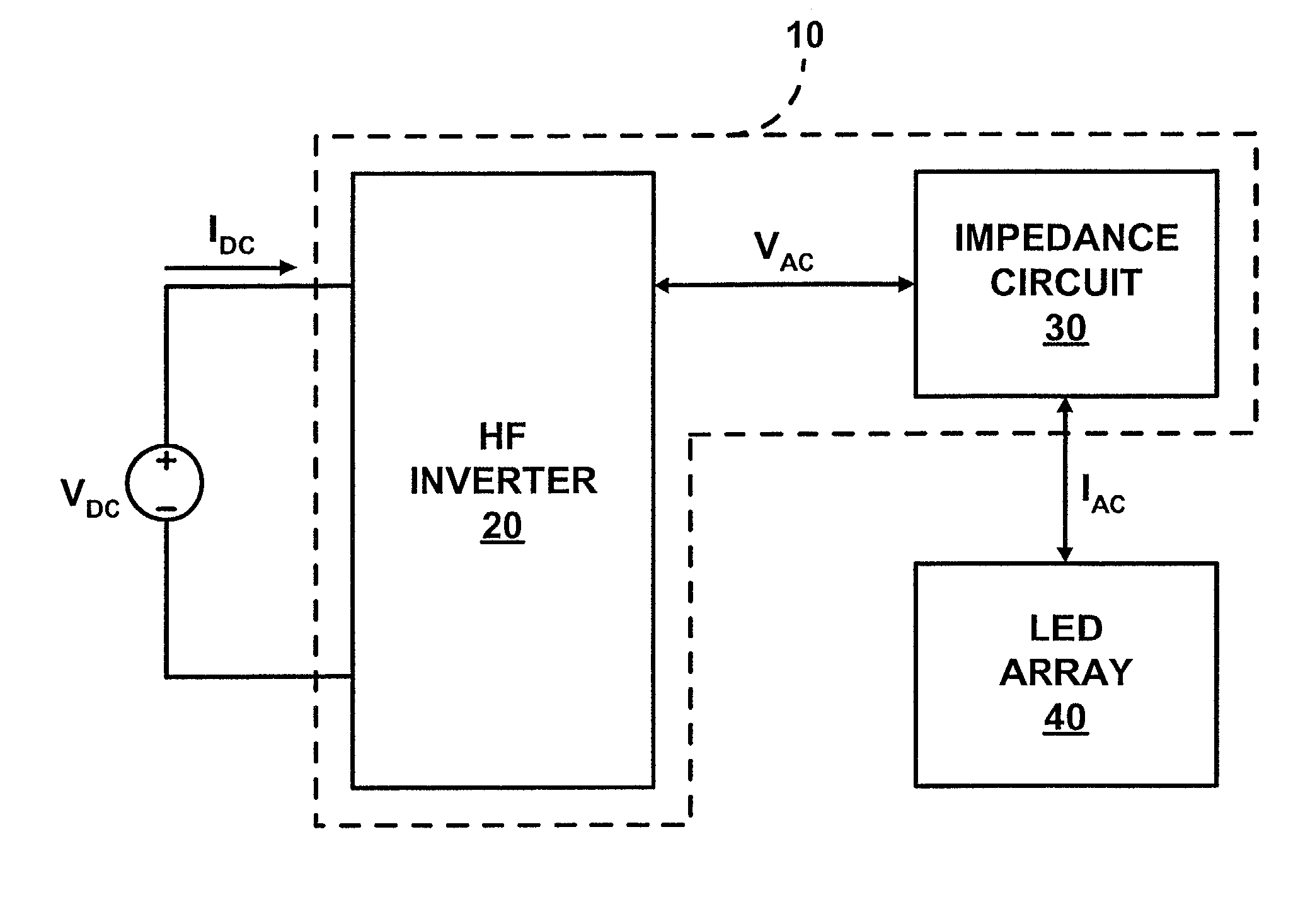
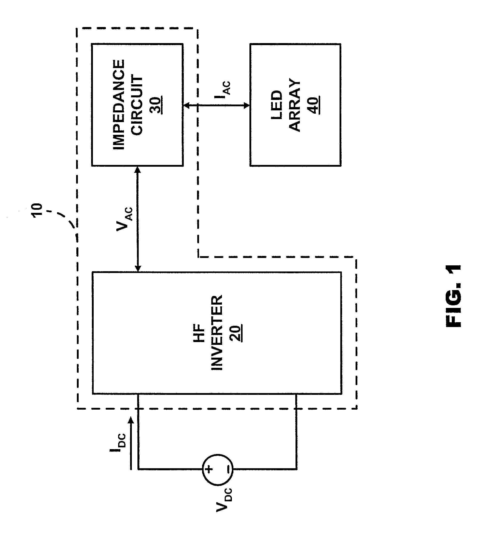
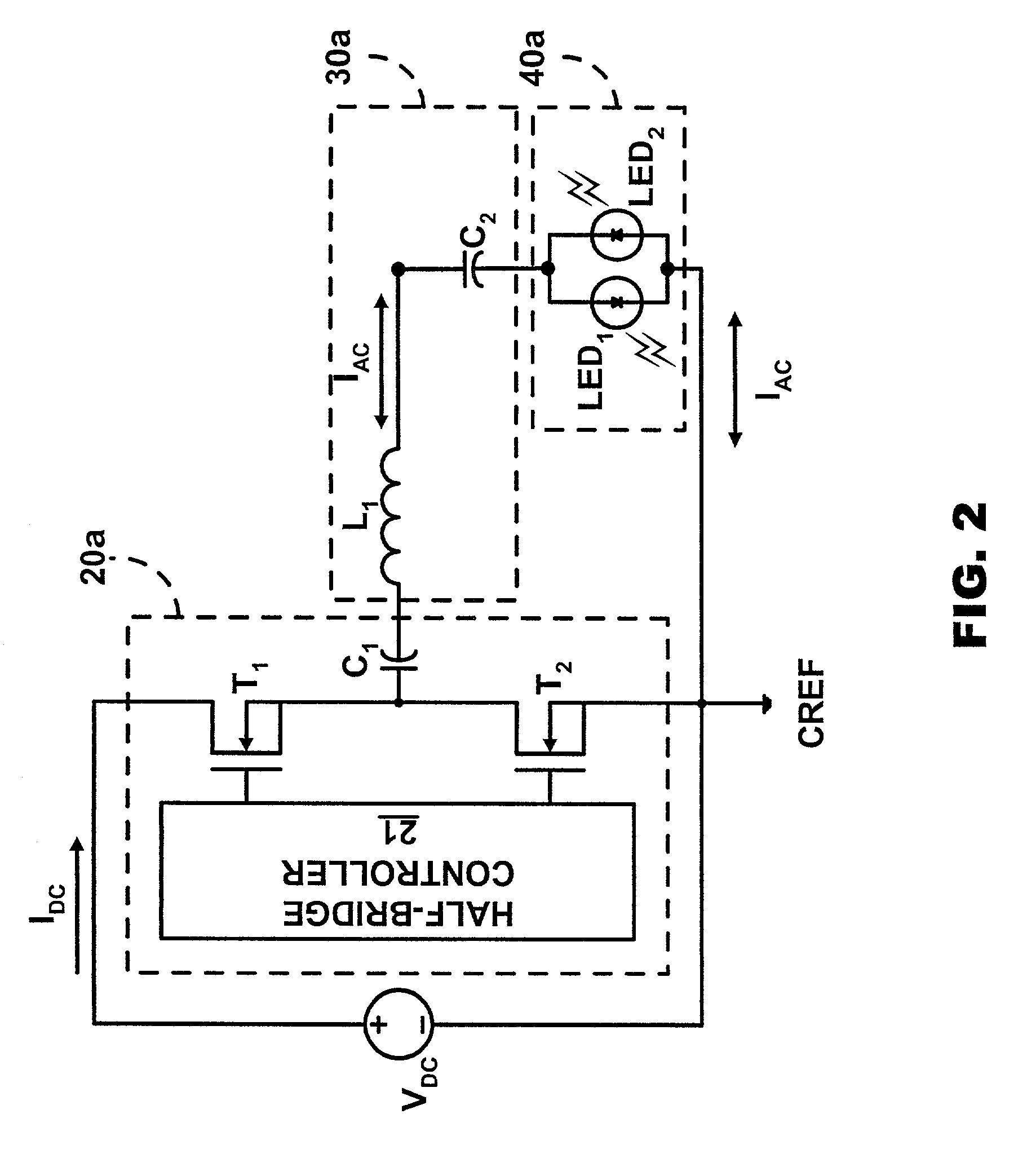
[0019] FIG. 2 illustrates LED driver 10 (FIG. 1) in accordance with the present invention. A HF inverter 20a includes a half-bridge controller 21 for controlling a half-bridge consisting of a transistor T.sub.1 and a transistor T.sub.2 in the form of MOSFETs. HF inverter 20a conventionally activates and deactivates transistor T.sub.1 and transistor T.sub.2 in an alternating inverse manner to produce a DC pulsed voltage (not shown) between transistor T.sub.1 and transistor T.sub.2. The DC pulsed voltage is dropped across a capacitor C.sub.1 to produce a voltage square wave (not shown) to an impedance circuit 30a.
[0020] An impedance circuit 30a includes an inductor L.sub.1 and a capacitor C.sub.2 coupled to capacitor C.sub.1 in series. Inductor L.sub.1 and capacitor C.sub.2 direct a flow of alternating current I.sub.AC through a LED array 40a having a light emitting diode LED.sub.1 and a light emitting diode LED.sub.2 coupled in anti-parallel (i.e., opposite polarizations). Alternatin...
second embodiment
[0023] FIG. 4 illustrates LED driver 10 (FIG. 1). An impedance circuit 30b includes inductor L.sub.1 coupled in series to a parallel coupling of capacitor C.sub.2, a capacitor C.sub.3 and a capacitor C.sub.4. Impedance circuit 30b directs a flow of alternating current I.sub.AC through LED array 40c. An anti-parallel coupling of light emitting diode LED.sub.1 and light emitting diode LED.sub.2 is coupled in series with capacitor C.sub.2. An anti-parallel of coupling light emitting diode LED.sub.3 and light emitting diode LED.sub.4 is coupled in series with capacitor C.sub.3. An anti-parallel coupling of light emitting diode LED.sub.5 and light emitting diode LED.sub.6 is coupled in series with capacitor C.sub.4. Divided portions of alternating current I.sub.AC flow through light emitting diode LED.sub.1, light emitting diode LED.sub.3 and light emitting diode LED.sub.5 when alternating current I.sub.AC is in a positive polarity. Divided portions of alternating current I.sub.AC flow t...
third embodiment
[0025] FIG. 5 illustrates LED driver 10 (FIG. 1). An impedance circuit 30c includes inductor L.sub.1 coupled in series to a capacitor C.sub.5, which is coupled in series to a parallel coupling of capacitor C.sub.2, capacitor C.sub.3 and capacitor C.sub.4. Impedance circuit 30c directs a flow of alternating current I.sub.AC through of LED array 40d. An anti-parallel coupling of light emitting diode LED.sub.1 and light emitting diode LED.sub.2 is coupled in series with capacitor C.sub.2. An anti-parallel of coupling light emitting diode LED.sub.3 and light emitting diode LED.sub.4 is coupled in series with capacitor C.sub.3. An anti-parallel coupling of light emitting diode LED.sub.5 and light emitting diode LED.sub.6 is coupled in series with capacitor C.sub.4. A switch in the form of a transistor T.sub.3 is coupled in parallel to the anti-parallel LED couplings. Those having ordinary skill in the art will appreciate other forms of switches that may be substituted for transistor T.su...
PUM
 Abstract
Description
Claims
Application Information