An Exercise Apparatus

a technology of exercise equipment and adaptable parts, which is applied in the direction of resistance force resistors, gymnastic exercises, balance beams, etc., can solve the problems of limited development of resilient members, lack of interest of users, and limited user development, so as to increase reduce the resiliency of resilient members

Inactive Publication Date: 2003-07-03
REEBOK
View PDF77 Cites 34 Cited by
  • Summary
  • Abstract
  • Description
  • Claims
  • Application Information

AI Technical Summary

Benefits of technology

[0007]The adjustment mechanism includes a handle, a gear and ratchet assembly, and a plurality of locking mechanisms. Each of the locking mechanisms is arranged radially opposite of and attached to, via a ratchet, another of the locking mechanisms. Two of the locking mechanisms include inner ratchets, which allow the locking mechanisms to move relative to a gear. A centrally-located gear tracks both of the ratchets. The gears and ratchets allow for synchronized movement of the locking mechanisms between an engaged position and a disengaged position.
[0008]Use of the adjustment mechanism changes the resiliency of the resilient member. During adjustment, the locking mechanisms move radially along a ratchet of the gear and ratchet assembly. There are two settings available for the locking mechanisms, an engaged setting and a disengaged setting. When the mechanism is adjusted inwardly (e.g., engaged), the locking mechanisms move radially inwardly to engage the resilient member, thereby increasing the resiliency of the resilient member. When the mechanism is adjusted outwardly (e.g., disengaged), the locking mechanisms move radially outwardly to disengage the resilient member, thereby decreasing the resiliency of the resilient member.

Problems solved by technology

While many of these designs promote the development of the user's muscles and balance, the extent of such development is limited by the basic design of the apparatus.
The design of the apparatus often limits the amount of development of the user and can also lead to a lack of interest of the user.

Method used


Image

  • An Exercise Apparatus
  • An Exercise Apparatus
  • An Exercise Apparatus

Examples


Embodiment Construction

[0021] [0019]A preferred embodiment of the present invention is now described with reference to the figures, where like reference numbers indicate identical or functionally-similar elements. While specific configurations and arrangements are discussed, it should be understood that this is done for illustrative purposes only. A person skilled in the relevant art will recognize that other configurations and arrangements can be used without departing from the spirit and scope of the invention.

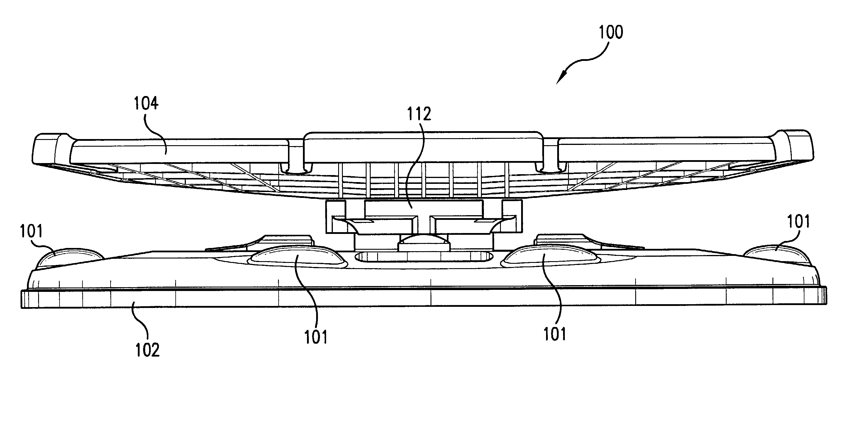
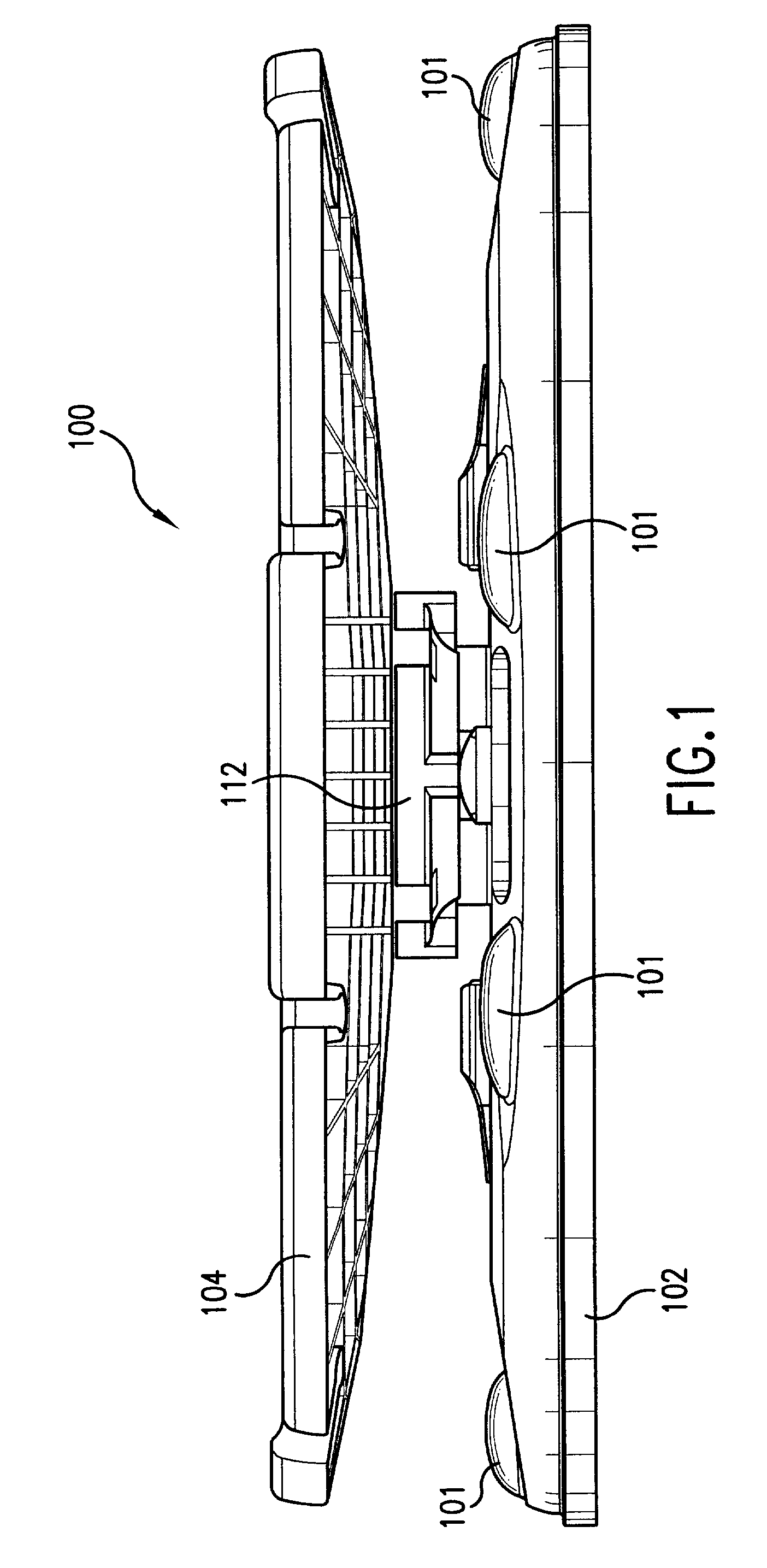
[0022] [0020]Referring to the drawings, FIG. 1 depicts a side view of an exercise apparatus 100 of the present invention, which includes a base 102, with bumper pads 101, a platform 104 disposed above base 102, and a resilient member 112 disposed between base 102 and platform 104. In one embodiment, platform 104 and base 102 are composed of an aluminum honeycomb material, thereby making apparatus 100 light-weight and strong. In this embodiment, a composite is formed from an aluminum honeycomb core...


PUM


Abstract

Abstract of Disclosure An exercise apparatus including a base, a platform, and a resilient member located between and attached to both the base and the platform. The resilient member can rotate, twist, and tilt in every angle while also providing a resistance force to all degrees of movement. The platform may be modified by the addition of an elastomeric material over its surface to provide additional traction or padding. The platform may also have notches placed around its perimeter, through which resistance tubing or rope may be placed such that upper body resistance motion may be integrated into the exercise apparatus. Furthermore, support members may be disposed under both the platform and base for additional support and rigidity. The resilient member may have a flange, which in conjunction with an adjustment mechanism, may affect the amount of resiliency of the resilient member. The adjustment mechanism may have a handle, a gear and ratchet assembly, and a plurality of locking mechanisms. The adjustment mechanism may be simple and easy to use in that a single movement of the adjustment mechanism will simultaneously adjust the plurality of locking mechanisms and ultimately adjust the overall resiliency of the resilient member.

Description

Background of Invention[0001] Field of the Invention[0002] [0001]The present invention relates to the field of exercise equipment. In particular, it relates to an adjustable exercise apparatus for increasing an individual's strength, agility, balance, and cardiovascular endurance.[0003] Related Art[0004] [0002]There are many different activities in daily life that require individuals to use their strength, agility, and balance. Furthermore, many of today's sports require even more developed abilities. In order to improve upon the skills needed for these activities many people have turned to various forms of exercise equipment designed to isolate and target the areas of the body used in these activities.[0005] [0003]The initial movement in this area of exercise equipment led to the design of several different apparatuses concentrated on balancing. Similar designs have also been developed for use in physical therapy. While many of these designs promote the development of the user's mu...

Claims


Application Information

Patent Timeline
Patent Type & Authority Applications(United States)
IPC IPC(8): A63B22/18
CPCA63B2022/0033A63B22/18
Inventor FAN , JASPERHANCOCK , CHRISTOPHER M.HECOX , MARK G.
Owner REEBOK
Why Eureka
Try Eureka