Load-shifting vehicle

Inactive Publication Date: 2003-07-10
LANSBERRY TRACTOR
View PDF0 Cites 29 Cited by
  • Summary
  • Abstract
  • Description
  • Claims
  • Application Information

AI Technical Summary

Benefits of technology

0016] An electronic controller is operable to receive the steering signals generated by the steering and signal generating mechanism and to responsively control the power supplied from the engine assembly to the retractable and extensible units to move said wheels between said rectracted and extensible units and effect a load shift between the wheels and the track assembly so that (1) when a straight steering signal is receive

Problems solved by technology

Although capable of moving over terrain having a variety of soil conditions conventional wheel-driven vehicles frequently become stuck because all of the tractional forces and driving surfaces of the wheels are not always put to the ground.
Conventional four wheel vehicles and conventional two track vehicles often cause environmental damage when used in natural areas.
Recently, environmental concerns have been raised about the disruption of the topsoil which occurs when conventional loader/bulldozer-type vehicles are operated on the topsoil, sand or other soft terrain o

Method used


Image

  • Load-shifting vehicle
  • Load-shifting vehicle
  • Load-shifting vehicle

Examples


Embodiment Construction

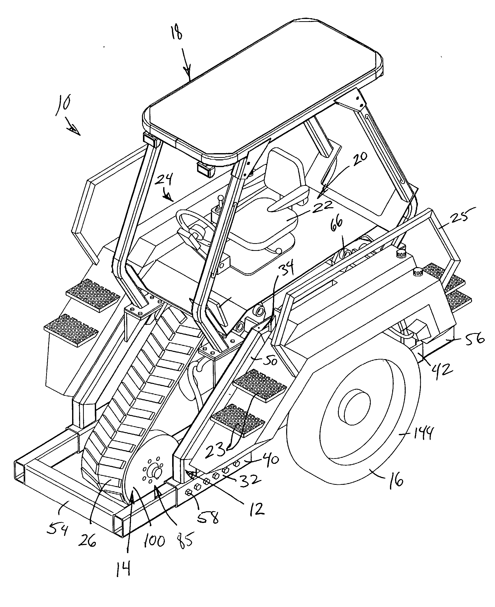
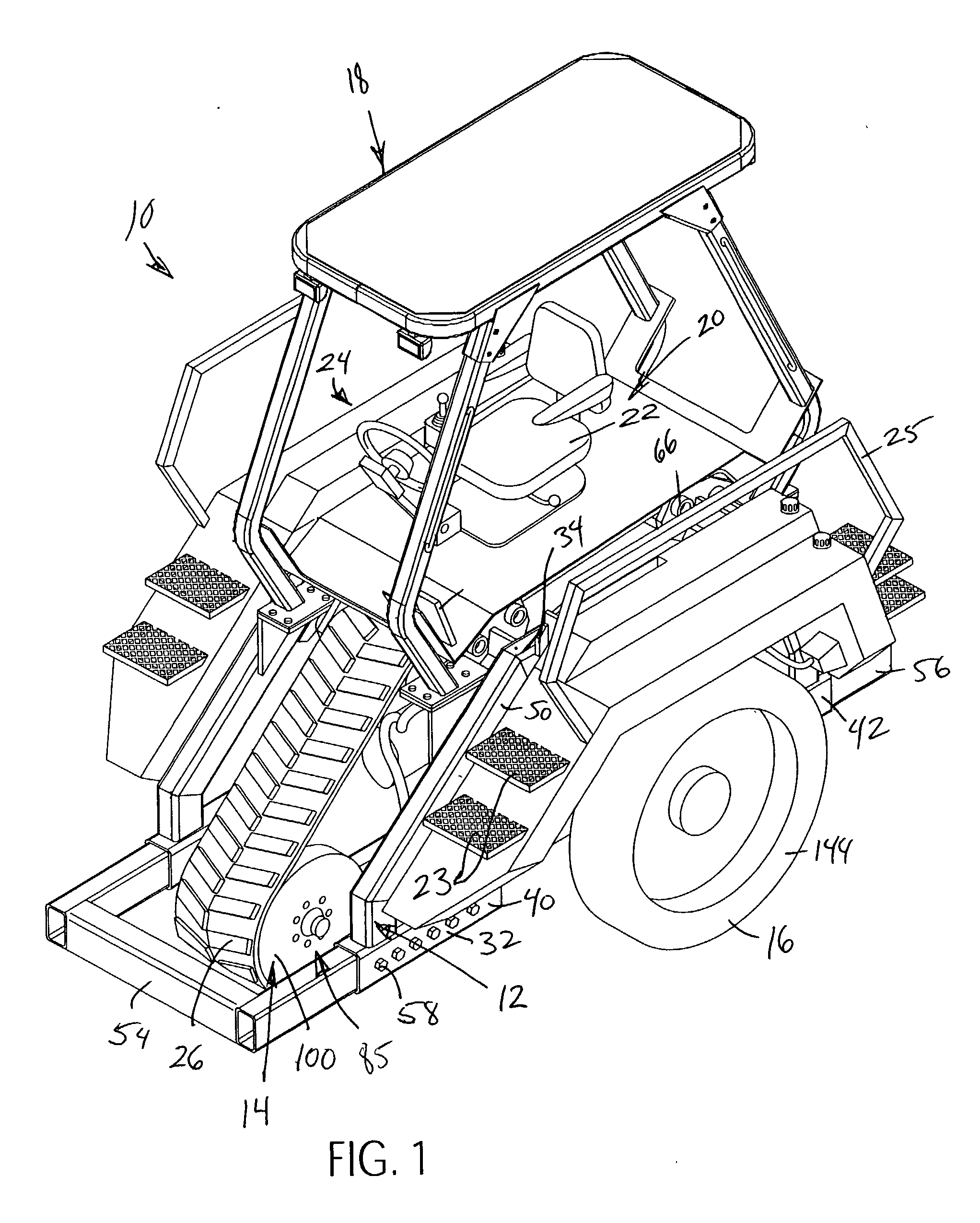
[0029] FIG. 1 is a left side perspective view (where the left and right directions are considered from the point of view of a forwardly facing vehicle operator) of a vehicle, generally indicated at 10, constructed in accordance with the principles of the present invention. The vehicle 10 is of the same general type as is disclosed in my U.S. Pat. Nos. 5,615,748 and 6,144,921, the entirety of each patent being incorporated into the present application in its entirety for all material disclosed therein.

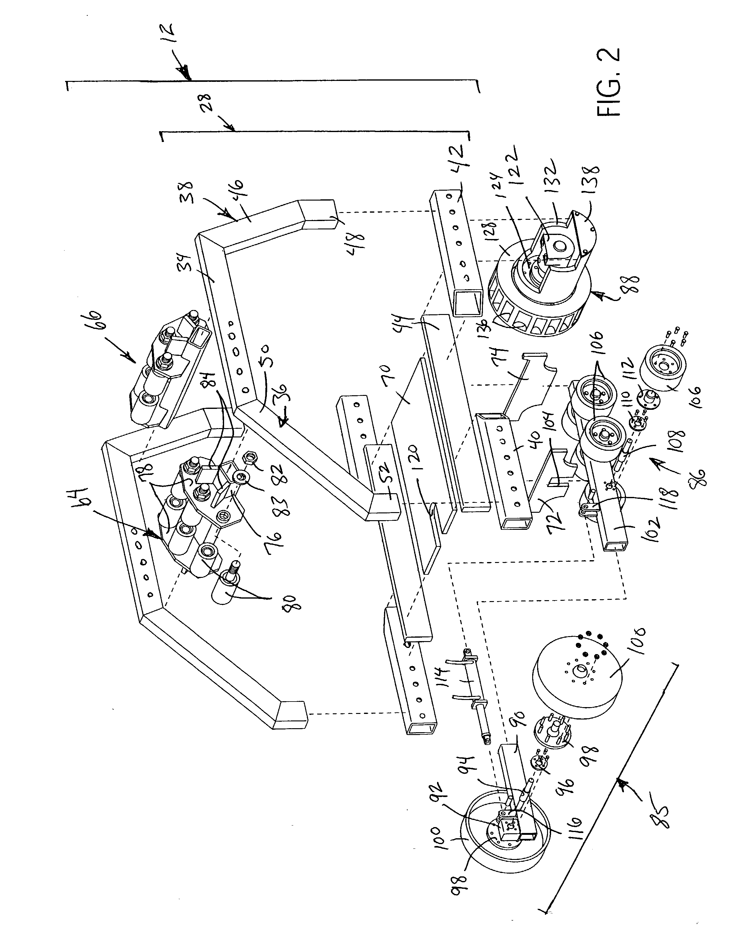
[0030] The vehicle 10 includes a main frame, generally indicated at 12, a driving track assembly, generally indicated at 14, mounted to the frame 12, and a pair of secondary driving assemblies, each generally indicated at 16, disposed on opposing lateral sides of the track assembly 14 in flanking relation therewith. A cab assembly 18 is mounted on top of the main frame 12 and includes an operator cockpit 20. The cockpit 20 includes an adjustable operator's seat assembly 22 and a plurali...


PUM


Abstract

A vehicle comprising a frame assembly supported for movement by a centrally located driving track assembly and a pair of flanking driving and steering wheels. An engine is assembly carried by the frame assembly which is constructed and arranged to generate and supply power for the vehicle. The driving track assembly includes a track frame structure forming a part of the frame assembly, a series of rollers carried by the track frame structure including a driver roller and an endless track trained about the rollers so as to provide an operative ground engaging flight extending in a straight vehicle driving direction. A power operated track moving structure is operatively connected to the driver roller using power supplied from said engine assembly to move said track in driving relation to the ground. A wheel mounting assembly is provided for each wheel including wheel mounting structure constructed and arranged to mount an associated wheel for rotational movement about a generally transversely horizontally extending rotational axis and a parallel linkage mechanism operatively connected with the frame assembly extending laterally outwardly in connected relation to the wheel mounting structure constructed and arranged to enable the wheel mounting structure to be vertically moved in such a way as to effect a vertical translational movement of the rotational axis. A power operated wheel driving structure is operatively connected with each wheel and uses power supplied by the engine assembly to rotate an associated wheel about the rotational axis thereof. A power operated retractable and extendible unit is operatively connected between the track frame structure and each wheel which is constructed and arranged to effect a relative vertical movement of an associated wheel with respect to the track frame structure between retracted and extended positions.

Description

FIELD OF THE INVENTION[0001] The present invention is generally related to vehicles and more particularly related to a vehicle for use on a wide range of terrain, including uneven and / or steep terrain having a variety of soil conditions. The vehicle of the present invention offers many advantages over conventional vehicles and can replace conventional vehicles in performing a variety of tasks.BACKGROUND OF THE INVENTION[0002] Most conventional vehicles such as agricultural tractors, front end loaders and bulldozers are either driven by four wheels or by a pair of laterally spaced. parallel tracks. Four-wheeled vehicles have a pair of laterally spaced front wheels and a pair of laterally spaced rear wheels that engage the ground and rotate during vehicle movement. Typically one or both pairs of wheels are driven to move the vehicle. The wheels of the wheel-driven vehicles are generally large and have tread designs that aid in moving the vehicle over sand, clay and mud. Although capab...

Claims


Application Information

Patent Timeline
IPC IPC(8): B62D49/06B62D55/02
CPCB62D55/02B62D49/0635
Inventor LANSBERRY, JOHN B.
Owner LANSBERRY TRACTOR
Why Eureka
Try Eureka