System and method of estimating the position of a mobile terminal in a radio telecommunications network

a mobile terminal and radio telecommunications network technology, applied in the field of telecommunication systems, can solve the problems of large modification of mobile terminals, inconvenient closed-form mathematical expression of functions, and high cost and complexity of their implementation into the existing cellular network infrastructur

Inactive Publication Date: 2003-07-10
UNWIRED PLANET
View PDF14 Cites 77 Cited by
  • Summary
  • Abstract
  • Description
  • Claims
  • Application Information

AI Technical Summary

Problems solved by technology

A major problem with existing solutions for locating mobile terminals is the high cost and complexity required for their implementation into the existing cellular network infrastructure.
Others require extensive modifications to mobile terminals and are inadequate du

Method used


Image

  • System and method of estimating the position of a mobile terminal in a radio telecommunications network
  • System and method of estimating the position of a mobile terminal in a radio telecommunications network
  • System and method of estimating the position of a mobile terminal in a radio telecommunications network

Examples


first embodiment

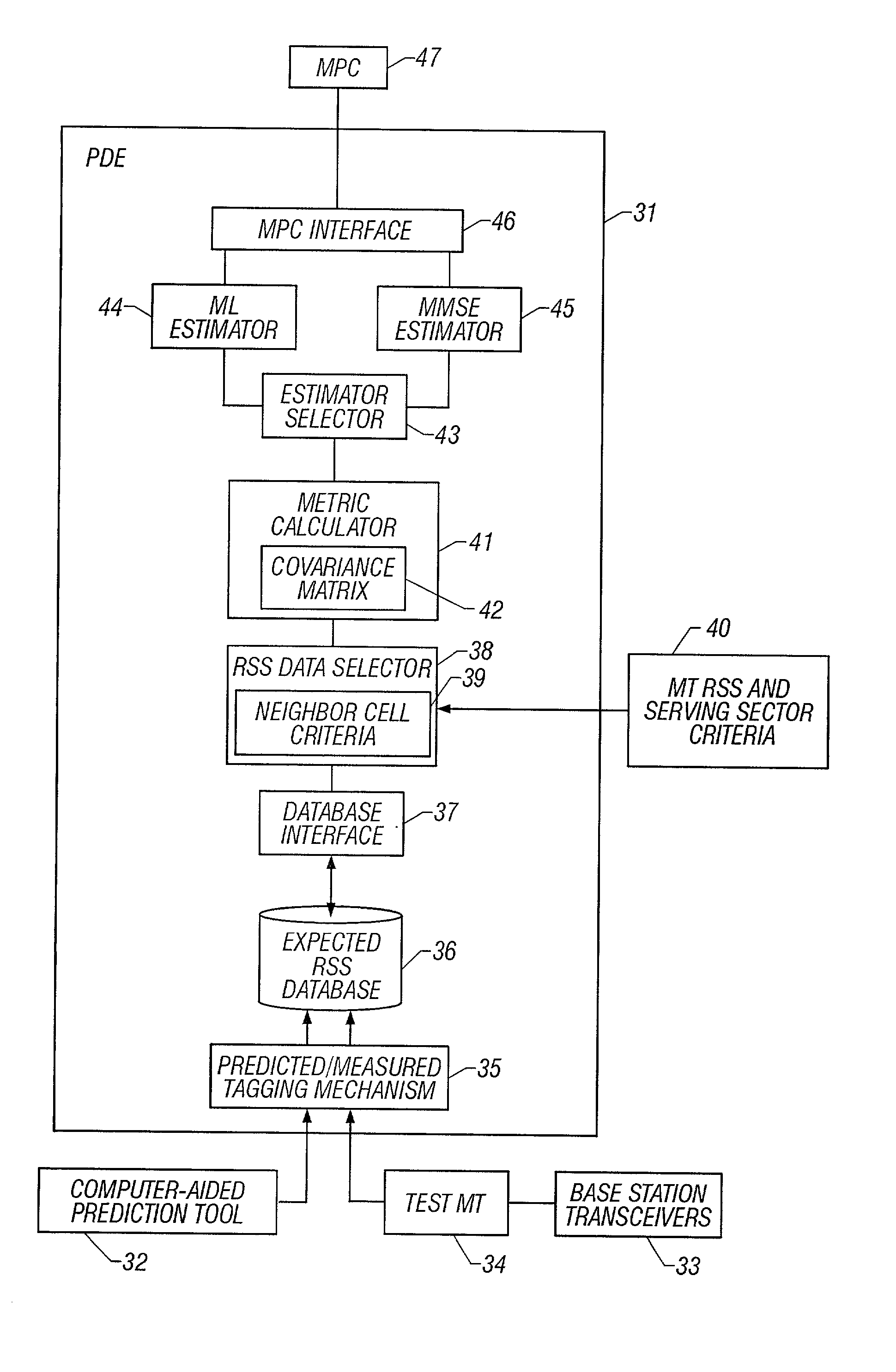
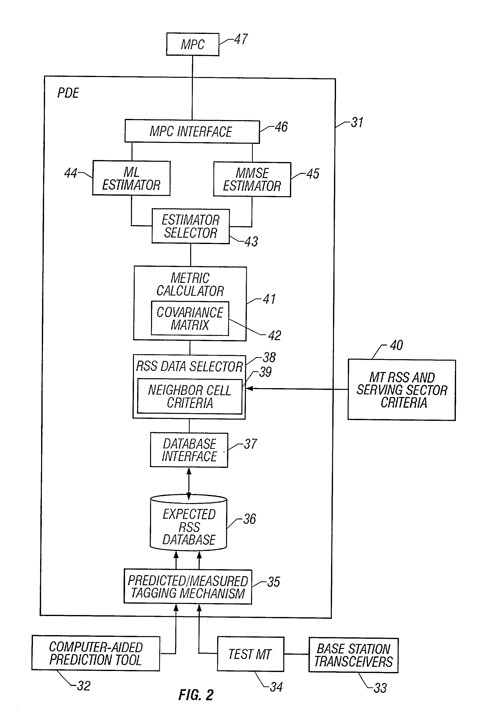
[0035] In the present invention, a separate covariance matrix is stored for each database entry to compute the metrics for each of the locations in the database. When a metric has to be computed for a certain location, the covariance matrix for the corresponding entry is used by extracting the sub-matrix of the covariance matrix whose rows and columns correspond to the sectors that are common between the database entry and the sectors used for the measurement set, r. For example, if the stored covariance matrix is a 3.times.3 matrix for the sectors 1, 2 and 3, and the measurements were made on sectors 1 and 3, then, the sub-matrix contains the elements of the covariance matrix indexed by the pairs (1, 1), (3, 3), (1, 3) and (3, 1). This sub-matrix is then used in computing the value of p(r.vertline.x.sub.k) in order to compute the metric m.sub.k.

[0036] In a second embodiment of the present invention, two covariance matrices are stored for the whole database to compute the metrics fo...

third embodiment

[0037] In the present invention, the covariance matrix is assumed to be a diagonal matrix with different elements for each sector. If the non-diagonal elements, x.sub.ij, (i.noteq.j) of a square matrix are all zero, the matrix is a diagonal matrix. For example, the following matrix is a diagonal matrix: 2 E ( x x ) 0 0E ( y y )

[0038] As can be seen from this example, there is only the need to store as many elements as there are variables. Thus, the storage size for the covariance matrix is reduced significantly.

[0039] For the present invention, the variables are the errors in the RSS for each of the sectors. Hence, instead of storing a matrix, a single variance value may be stored per sector per location. Assuming, as in the first embodiment above, that the variance is location dependent, a single value is stored for the expected measurement variance of each sector at each location or entry in the database. For example, if there are 20 sectors in the whole system, and 100 locations ...

fifth embodiment

[0041] In the present invention, a single value is used for the variance of all sectors, i.e., it is assumed that the covariance matrix is diagonal with all elements of the diagonal being the same. However, it is assumed that the variance values are different for measurement data and prediction data. Hence, in this embodiment, only two values are stored for the measurement variance. One value is used when computing metrics for entries populated with actual measurement data, and the other value is used when computing metrics for entries populated with prediction data.

[0042] Dynamic Switching of Algorithms

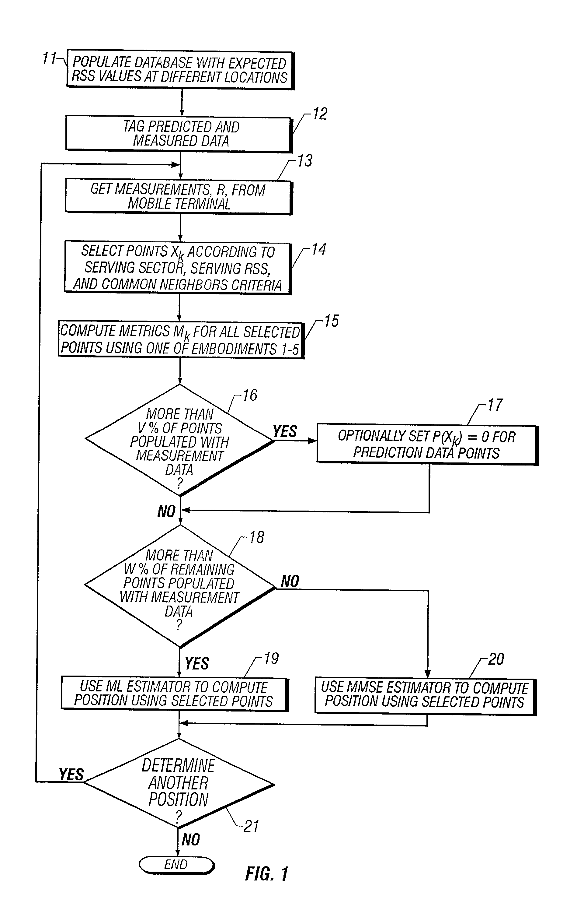
[0043] The selection of the ML or MMSE algorithms may be dynamically switched based on the positions being considered. When the position for a mobile terminal has to be computed, a set of points is selected from the database. Metrics are then computed for these selected points. Then, an ML or an MMSE estimator or some other type of estimator is used to compute the position of the mob...


PUM


Abstract

A system and method of estimating the position of a mobile terminal (MT) operating in a radio telecommunications network. Expected Received Signal Strength (RSS) values are predicted by a computer-aided prediction tool, and/or are measured by a test MT from base station transceivers. The predicted and measured RSS values are then tagged to indicate whether each value was predicted or measured. The RSS values are then stored at a plurality of locations in a database. When RSS measurements are received from the MT being located, a covariance matrix is used to compute metrics for the locations in the database. If more than a threshold percentage of the locations were populated with measured values, a Maximum-Likelihood (ML) estimator is used to estimate the position of the MT. If fewer than the threshold percentage of locations were populated with measured values, a Minimum-Mean-Square-Error (MMSE) estimator is used to estimate the position.

Description

[0001] 1. Technical Field of the Invention[0002] This invention relates to telecommunication systems. More particularly, and not by way of limitation, the present invention is directed to a system and method of estimating the position of a mobile terminal in a radio telecommunications network.[0003] 2. Description of Related Art[0004] In modern radio telecommunication systems, the service area is divided into cells, each of which is served by a base station transceiver. As mobile terminals move about the service area of the system, they are handed off from one cell to another so that there is no lapse in service. In times of emergency, it would be extremely useful to police or other emergency crews responding to the situation to have precise position information for the mobile terminal. For this reason, the Federal Communications Commission (FCC) has mandated that cellular carriers be able to locate the position of a mobile terminal operating in their service areas to within a few h...

Claims


Application Information

Patent Timeline
IPC IPC(8): H04W64/00
CPCH04W64/00
Inventor KOORAPATY, HAVISHWANG, WADEPANAKANTI, VISWANATHZHU, GUWEI
Owner UNWIRED PLANET
Why Eureka
Try Eureka