[0007] It is a another object of the invention to provide such a method and system having a first part, into which contrast fluid from a bulk container is loaded, that can be used repeatedly with multiple patients without jeopardizing sterility of the system or remaining supply of contrast fluid, and a second part that is intended for a single use with a single patient.
[0008] It is a further object of the invention to provide such a two part system in which the relative manufacturing cost of the second, single-use part is considerably less than the manufacturing cost of the first, multiple-use part, thereby maximizing efficient management of contrast fluid delivery costs for the health care provider.
[0009] It is a still another object to provide such a method and system in which the single-use disposable part, which is replaced for each patient, is relatively simple to use and inexpensive to manufacture yet provides high reliability and operating integrity.
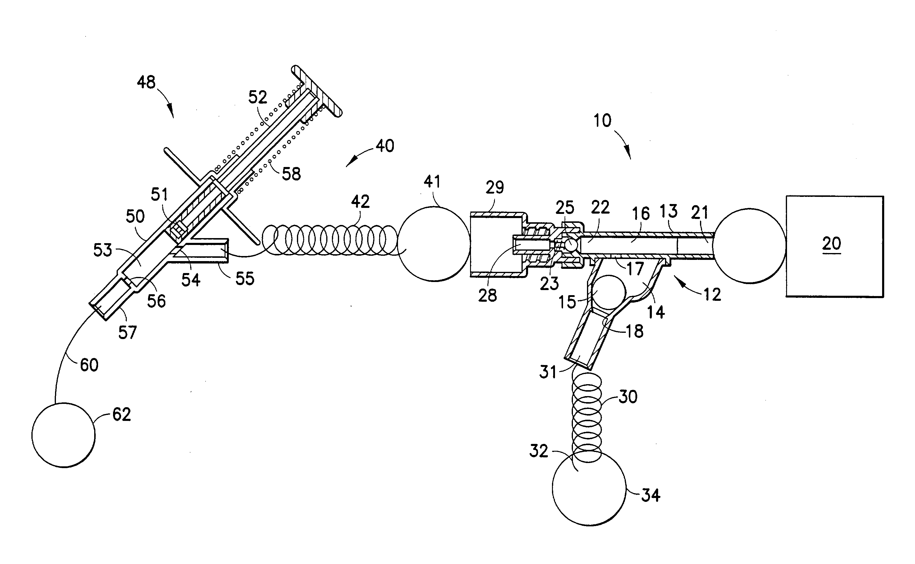
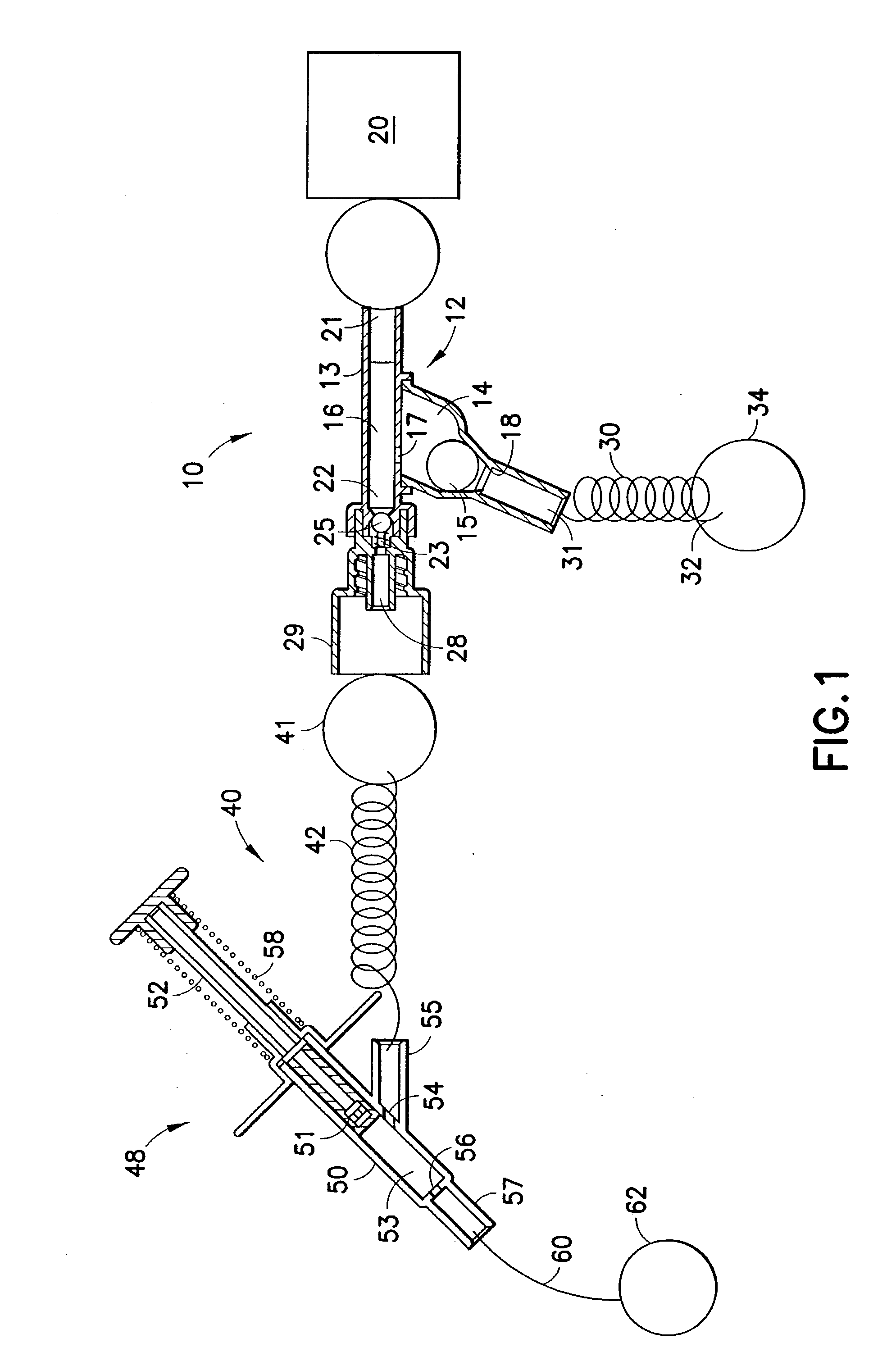
[0010] The present invention is based on and requires reliable maintenance of fluid flow, in at least that portion of the inventive apparatus into which contrast fluid is loaded from the fluid container or source, in a single direction toward the patient while preventing all potentially-contaminating reverse flow, so that contamination of the syringe and the bulk contrast source can be prevented. Toward that end, a system constructed in accordance with the invention includes a first or filling section which attaches to the bulk contrast source (and to the power syringe), and a second or delivery section that is connected between and communicates contrast fluid from the filling section to the patient. In this manner any possibility of contamination between the delivery section and the filling section is prevented. It is generally contemplated that the filling section will be used for multiple patients during an entire day of imaging procedures or operations, whereas the delivery section will be discarded and replaced after each patient use.
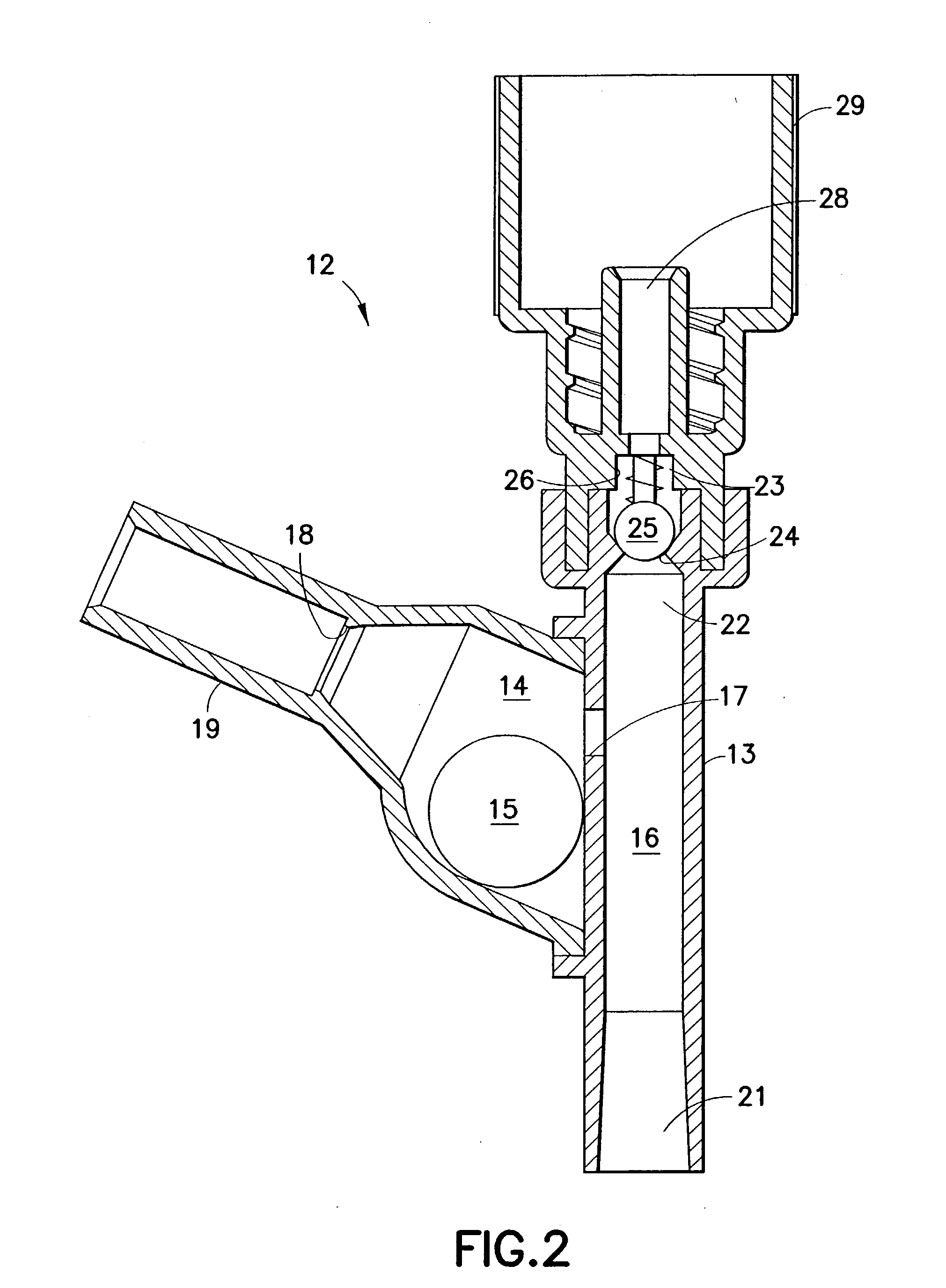
[0011] The filling section includes a main body that can be attached to any existing power or manually-operated syringe or injector, and the body defines a fluid holding chamber having an inlet and an outlet for the contrast fluid. The inlet is connected to a conventional or otherwise suitable vented spike, which is routinely used to pierce a contrast fluid container to access its contents for transfer of the contained fluid to another device, as by or through a coiled length of sterile medical tubing. The inlet is provided or associated with a gravity-operated valve formed by a stainless steel ball which seats in a conically-profiled ring or lip that surrounds or bounds the inlet. The ball rolls disengagingly off or away from the valve seat to thereby open the inlet when the main body is vertically tilted or oriented, whereupon the technician can use or operate the syringe to draw contrast fluid from the container into the filling section fluid chamber, and to then purge (back through the inlet) any air which has collected at the top of the fluid chamber. A spring loaded one-way check valve in or at or proximate the outlet insures that the purged air is directed toward the contrast container rather than downstream, toward the patient, to the delivery section of the inventive apparatus. The main body is then rotated or reoriented so that the contrast fluid outlet is disposed lower than the opposite end of the main body to which the syringe is connected, thereby activating or closing the gravity-operated ball valve and sealing closed the fluid path between the fluid holding chamber of the filling section and the contrast container. This orientation of the filling section additionally insures that any air that may yet be present in the fluid chamber rises to and remains at that portion of the main body to which the syringe is attached--i.e. remote from the outlet through which the contrast fluid is transferred to the delivery section of the apparatus--to thereby prevent unintended and potentially fatal injection of air into the patient. The filling section is then ready to be connected to the delivery section for injection or infusion of the contrast agent into the patient.
[0012] The delivery section includes a first fluid conduit--such as coiled, flexible, sterile tubing--having a first end that is attached to the outlet of the main body via at least one one-way check valve, and a second end that is attached to the inlet of an inline aspiration syringe. The aspiration syringe has a fluid chamber which is filled via an inlet and an outlet which is attached to a catheter by a second or delivery conduit in the form of another length of flexible, sterile, typically coiled tubing. The entire delivery system receives contrast fluid for infusion into the patient by means of the power or manually-operated loading syringe that is connected to the main body of the filling section. The aspiration syringe itself includes a spring loaded plunger which is used to confirm patency of the fluid path by manually depressing the plunger against the urgency of the spring and then releasing it to return the plunger to its initial position; patency is indicated by a visually-observable flow of blood from the patient into the second conduit for a distance of several inches. The process of injection or infusion, under the power of the main loading syringe, may then proceed. The aspiration syringe is furthermore constructed to avoid the need for additional valves, as have heretofore been required, to separately close its inlet during the patency confirmation; with the plunger itself blocks and thereby closes the inlet--and thus prevents backflow into the first conduit--as the plunger is advanced from its initial position to inject contrast fluid into the patient and then returned to that initial position to draw a mixture of contrast fluid and patient blood back into the aspiration syringe fluid chamber. The delivery section or set is moreover low in cost, as contrasted with the relatively more costly and complex filling section, and is intended to be discarded and replaced after each patient use of the inventive apparatus.

