Aircraft fluid drip pan system

a drip pan and fluid technology, applied in the field of aircraft fluid drip pan system, can solve the problems of affecting the environment, affecting the parking surface, and affecting the operation of aircraft, and achieve the effect of effectively fixing the drip pan, preventing the movement of the pan by wind, and effective positioning of the drip pan

Inactive Publication Date: 2003-07-31
BEMIS CHRISTOPHER L
View PDF2 Cites 8 Cited by
  • Summary
  • Abstract
  • Description
  • Claims
  • Application Information

AI Technical Summary

Benefits of technology

0008] It is a further object and feature of the present invention to provide such a system that provides an effective means to dispose of such accumulations at the convenience of the operator or maintenance crews.
0009] It is another object and feature of the present invention to provide such a system that addresses the need for a place of temporary containment of fuel contaminants.
0010] It is a further object and feature of the present invention to provide such a system that incorporates a cutout for a l

Problems solved by technology

When the aircraft is parked in a hangar or tied down on a tarmac, these fluids will commonly leak from the engine compartment, normally in small quantities.
The pavement surface, usually asphalt, absorbs these petroleum drippings and is affected by that absorption to the detriment and degradation of the parking surface and even of the environment.
This practice is no longer acceptable in these e

Method used


Image

  • Aircraft fluid drip pan system
  • Aircraft fluid drip pan system
  • Aircraft fluid drip pan system

Examples


Embodiment Construction

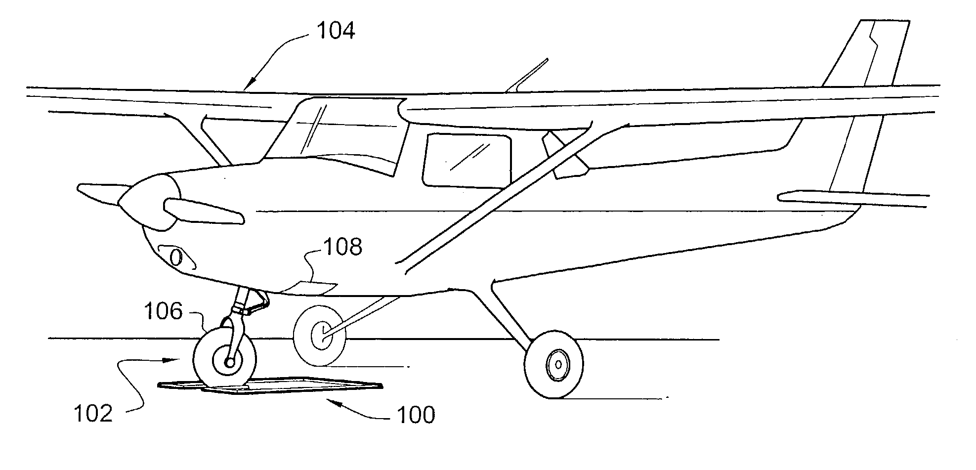
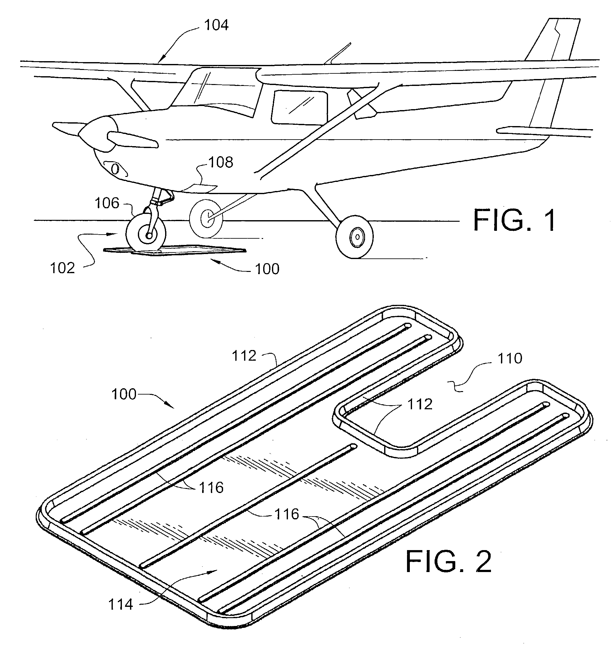
[0034] Reference is now made to the drawings. FIG. 1 is a perspective view of drip pan system 100 positioned around the front wheel area 102 of aircraft 104 according to a preferred embodiment of the present invention. Because the engine compartments of light aircraft are typically located above the nose wheel 106 of single engine aircraft, as shown, and commonly adjacent to the main landing gear wheels of twin-engine aircraft, conventional drip pans intended for use by automobiles cannot be used, not having an accommodation for the wheel. Preferably, drip pan system 100 is adapted to permit effective positioning under the engine compartment 108 of aircraft 104 by incorporating peripheral wheel cutout 110, as shown in FIG. 2.

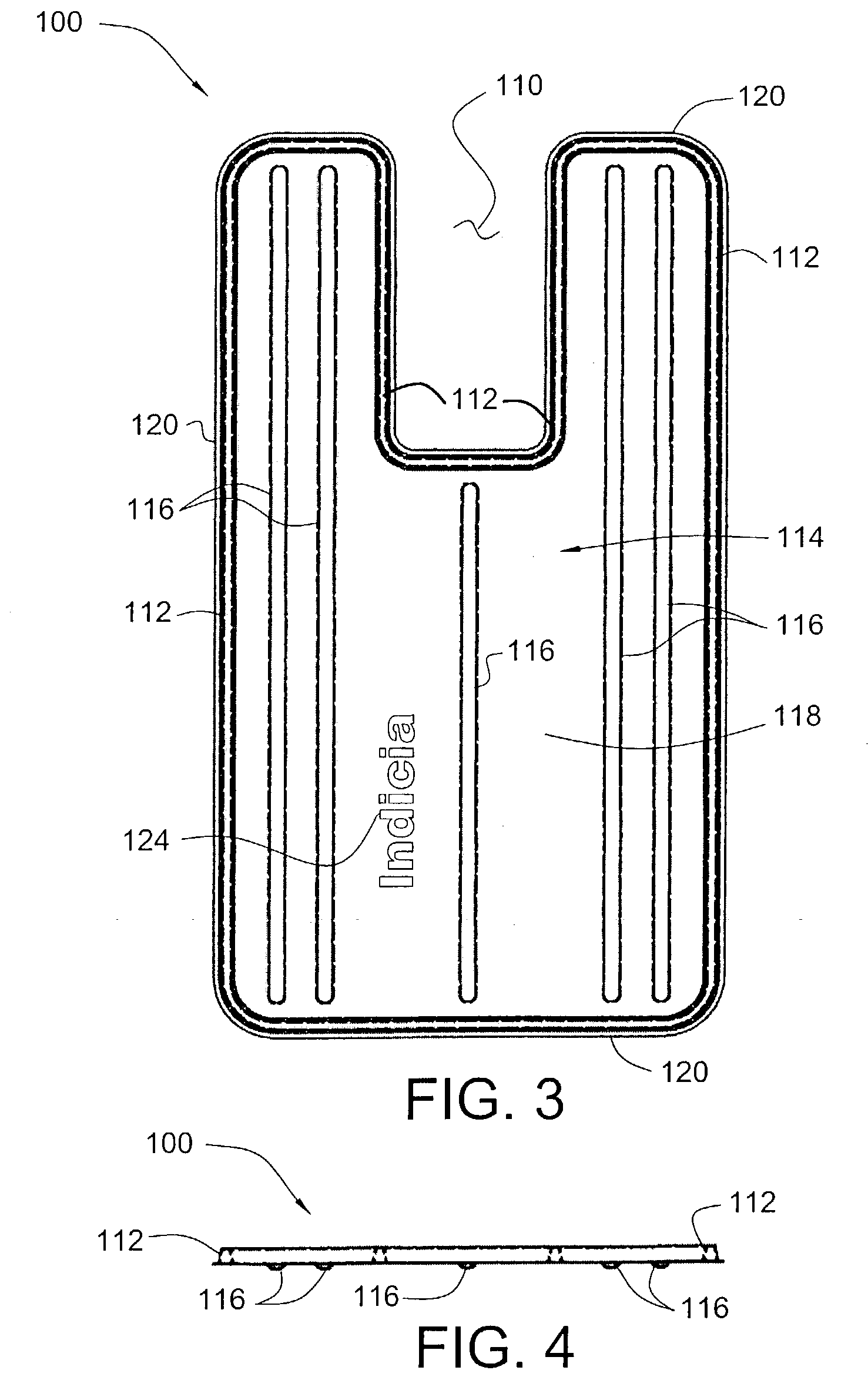
[0035] FIG. 2 is an isometric view of the drip pan system 100 (embodying herein fluid retaining means for retaining the fluids discharged from the aircraft; and also embodying herein at least one fluid retainer structured and arranged to retain the fluids discha...


PUM


Abstract

A system for improved collection and containment of fluids such as oils that commonly drip from an aircraft during service maintenance operations and during normal periods of storage. The system comprises a ground-supported drip pan incorporating a peripheral cutout adapted to accommodate a landing wheel of the aircraft to permit effective positioning under the engine. An embodiment for exterior use utilizing the weight of the aircraft to prevent movement of the system is also disclosed.

Description

[0001] The present application is related to Applicant's prior U.S. Provisional Application No. 60 / 341,100, filed Nov. 29, 2001, entitled "AIRCRAFT OIL DRIP PAN", and U.S. Utility Application No. 10 / 307,056, filed Nov. 29, 2002, the contents of which are herein incorporated by reference and are not admitted to be prior art with respect to the present invention by their mention in this cross-reference section.[0002] This invention relates to providing a system for improved collection and containment of fluids, such as oils, that commonly drip from an aircraft during service maintenance operations and during normal periods of storage.[0003] Typically, aircraft engines as well as other internal combustion engines employ oil, whether natural or synthetic, and sometimes other fluids for lubrication and cooling. When the aircraft is parked in a hangar or tied down on a tarmac, these fluids will commonly leak from the engine compartment, normally in small quantities. Even in small amounts,...

Claims


Application Information

Patent Timeline
IPC IPC(8): F16N31/00
CPCY10T428/24322F16N31/002
Inventor BEMIS, CHRISTOPHER L.
Owner BEMIS CHRISTOPHER L
Why Eureka
Try Eureka