
Snap disc device

Inactive Publication Date: 2003-08-07
SCHWAB KOPLIN ASSOC
View PDF0 Cites 30 Cited by
  • Summary
  • Abstract
  • Description
  • Claims
  • Application Information

AI Technical Summary

Benefits of technology

[0020] Another object of some embodiments is to provide a cloverleaf disc with radial protrusions around its outer perimeter that provide the disc with more freedom to deflect.
[0022] Another object of some embodiments is to provide a disc fastener with ample travel and a significant spring rate even though the disk has a rather large diameter to thickness ratio.
[0023] Another object of some embodiments is to provide a disc fastener whose material thickness is less than 5% of its diameter, thereby making the disc especially useful where axial space is limited.
[0044] FIG. 20 is similar to FIG. 19, but with a set of discs stacked in such a way as to provide a lower spring rate.

Problems solved by technology

The use of conventional compression springs can be limited by their physical size, as such springs are usually much longer than other types of springs.
This limits the use of Bellville washers to applications requiring relatively high forces and little travel.
Belleville washers can be stacked back-to-back to provide lower spring rates and more travel, but a stack of washers will of course consume more space.
However, stacking curved disc springs to achieve even lower spring rates can be difficult to accomplish.
Stacking the springs peak-to-peak is difficult to maintain, as the discs are normally free to rotate to a more stable arrangement of peak-to-valley.
Just as with curved disc springs, it can be difficult to maintain a stack of wave disc springs in a peak-to-peak arrangement.
The fingers, however, may also interfere with being able to effectively stack finger disc springs with predictable results.
The physical structure of conventional disc springs limits their application.
Current disc springs have limited use as springs and are not readily adapted for other uses such as gripping a square key.
However, the physical structure, operating characteristics, and / or method of pre-stressing such snap discs limits their usefulness.

Method used


Image

  • Snap disc device
  • Snap disc device
  • Snap disc device

Examples


Embodiment Construction

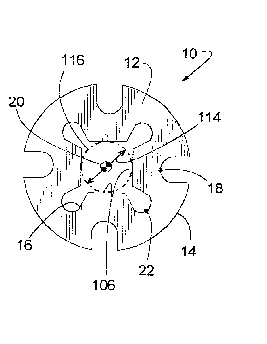
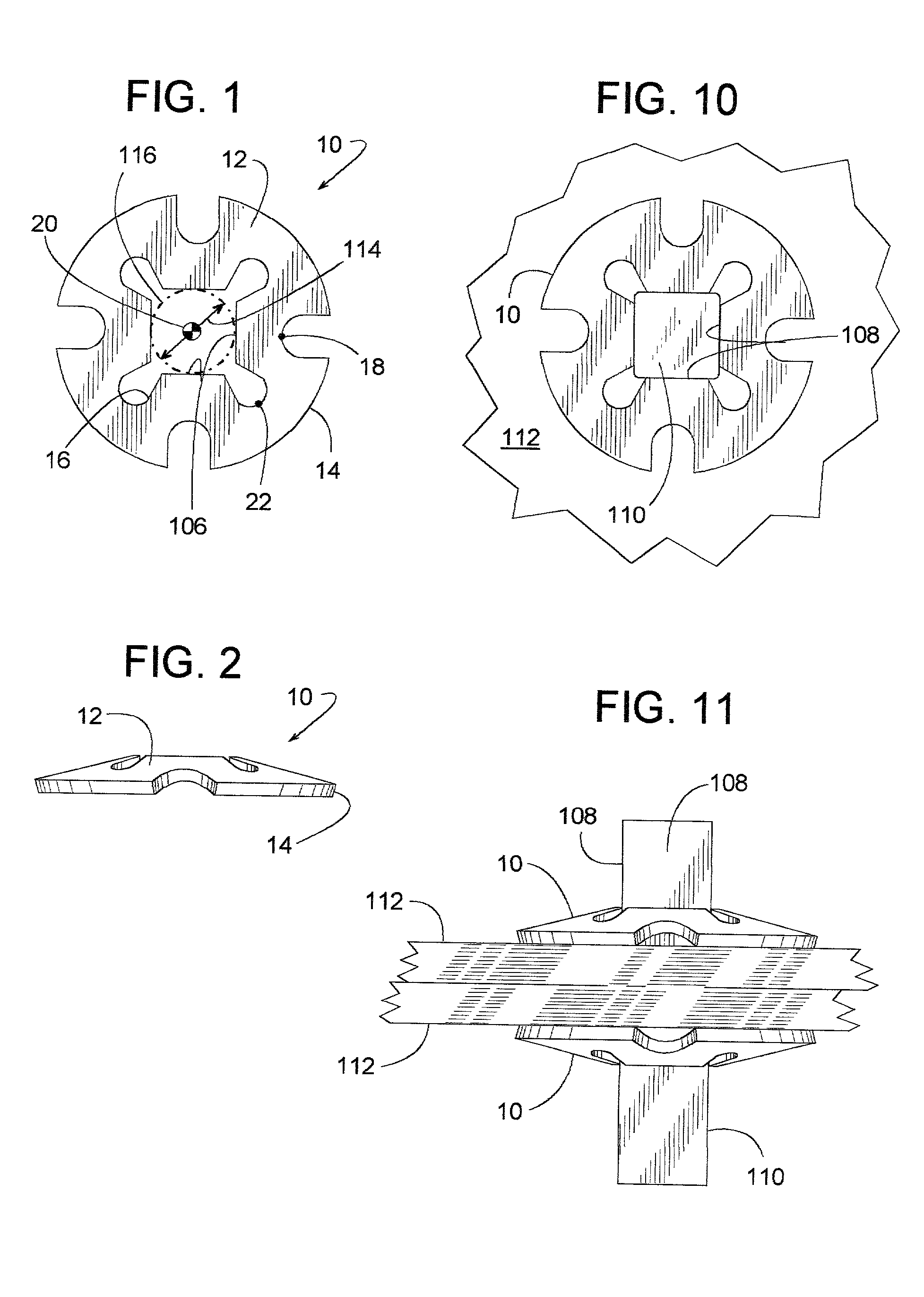
[0045] A fastener shown in FIGS. 1 and 2 includes a disc 10 with various design features that provide the fastener with the versatility to perform a variety of functions. Disc 10 (as shown or with some modification) can selectively serve as a variety devices including, but not limited to, a compression spring, a shaft or bar locking element, or tightness indicator for a threaded fastener.

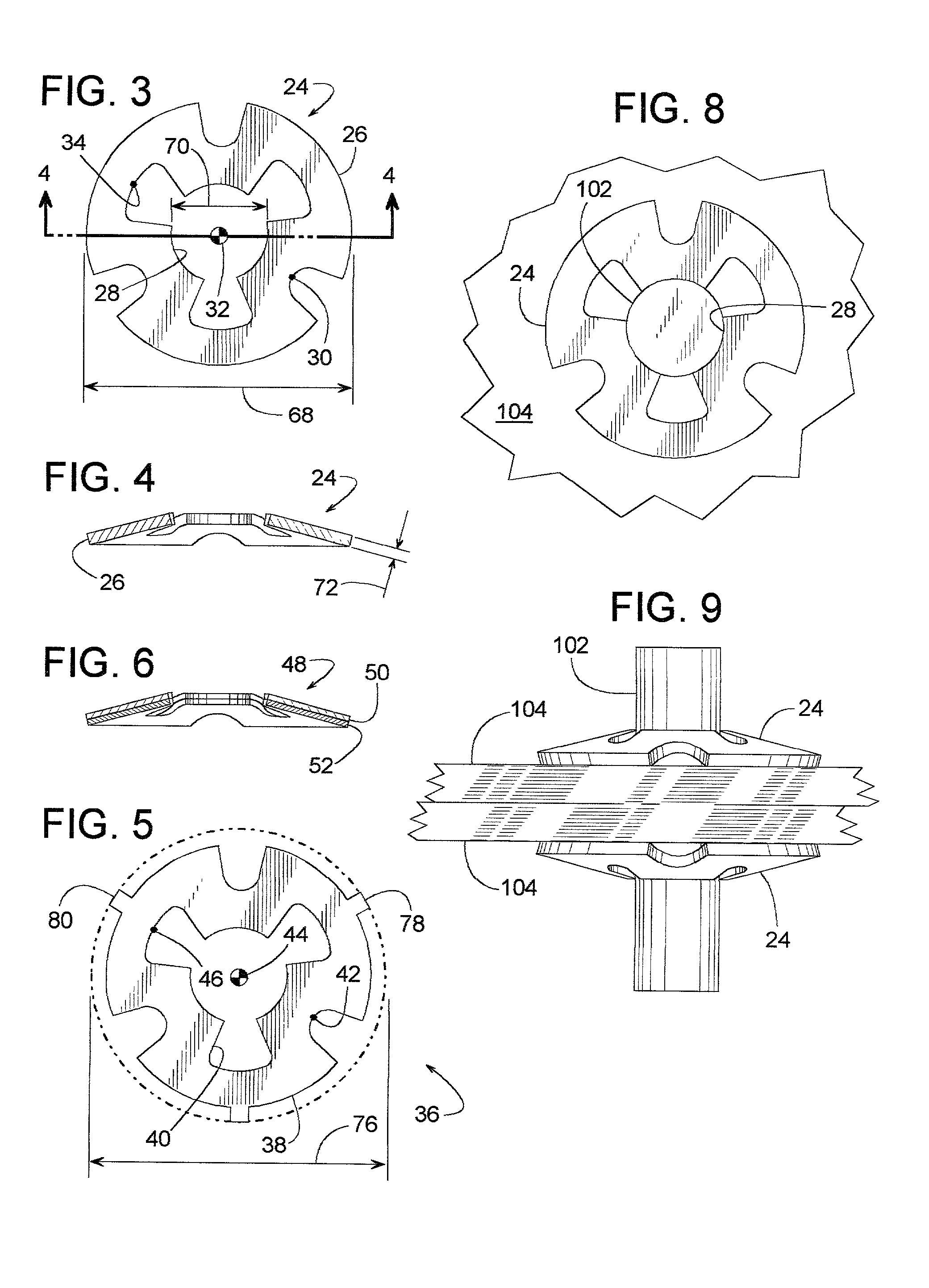
[0046] Disc 10 is preformed so that its face surface 12 assumes a bowed or conical shape when in its unstressed position of zero percent (i.e., the disc's natural relaxed state, as shown by various discs in FIGS. 1, 2, 3, 4, 5, 12, 13 and 16). A fully stressed position of 100% is where a disc is completely flattened out, as shown in FIG. 18. An intermediate position is when a disc is compressed to a position between its unstressed position of zero percent and its fully stressed position of 100%. For example, FIGS. 14, 15 and 17 show a disc compressed to an intermediate position of 75%, wherein the d...


PUM


Abstract

A bowed snap-disc includes inner and outer perimeters that provide the disc with operating characteristics not found in comparably sized discs. At certain points along its circumference, the inner perimeter extends farther from the disc's center than certain other points of the disc's outer perimeter. This provides the disc with a unique combination of spring constant, compressive force, deflection and coefficient of compliance. The disc is particularly useful as a small, flat compression spring; a shaft or bar locking element; tightness indicator for a threaded fastener; or a lock washer.

Description

[0001] 1. Field of the Invention[0002] The subject invention generally pertains to a snap disc device, and more specifically pertains a snap disc device whose particular geometry provides exceptional operating characteristics.[0003] 2. Description of Related Art[0004] The use of conventional compression springs can be limited by their physical size, as such springs are usually much longer than other types of springs. So, in applications where space is limited, other types of springs are often used, such as Bellville washers, curved disc springs, wave disc springs, and finger disc springs.[0005] Belleville washers are resiliently compressible conical washers that provide a spring effect. For a given length, Belleville washers typically have much higher spring rates and significantly less travel than compression springs. This limits the use of Bellville washers to applications requiring relatively high forces and little travel. Belleville washers can be stacked back-to-back to provide...

Claims


Application Information

Patent Timeline
IPC IPC(8): F16B21/20F16B39/10F16B39/24F16B43/00F16F1/32
CPCF16B21/20F16B39/10F16F1/324F16B43/00F16B39/24
Inventor SCHWAB, PIERRE P.
Owner SCHWAB KOPLIN ASSOC
Learn More