
Secateurs

Inactive Publication Date: 2003-08-14
PRUNING SHEARS PRADINES
View PDF6 Cites 0 Cited by
  • Summary
  • Abstract
  • Description
  • Claims
  • Application Information

AI Technical Summary

Benefits of technology

[0006] An object of the present invention is to remedy the drawbacks of known secateurs and to propose secateurs of the above-specified type that facilitate cutting branches of large diameter while presenting a tip that presents smaller risk of breakage.
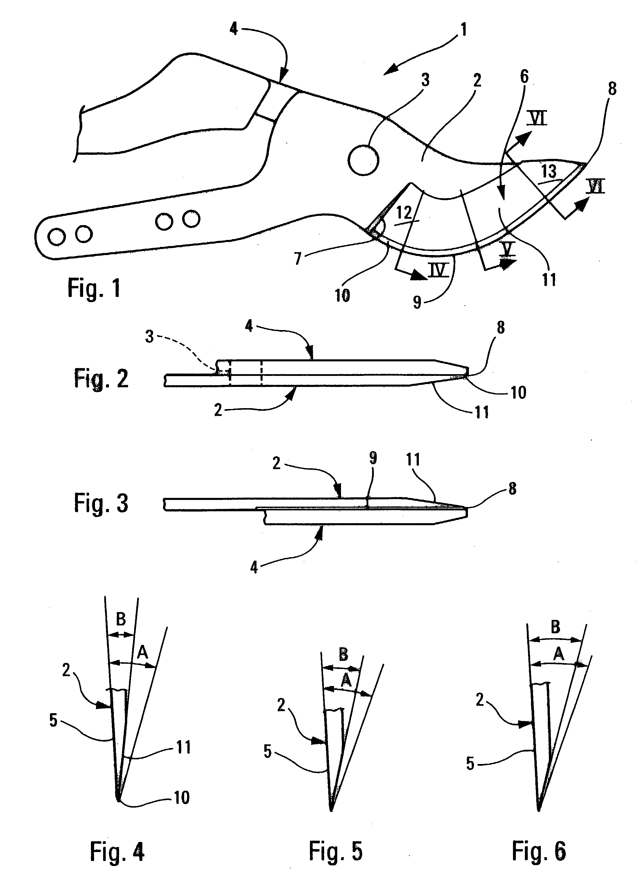
[0008] Thus, the region of the cutting blade close to the shoulder, which presents a second angle of minimum value and thus a minimum thickness, penetrates more easily into the wood, particularly into the wood of relatively stout branches. In contrast, the region of the cutting blade close to the tip of the cutting blade, in which the second angle has a maximum value, is of maximum thickness, and presents reduced risk of breakage.
[0009] In an advantageous version of the invention, the value of the second angle increases, e.g. in substantially regular manner, between the shoulder and the tip of the cutting blade.

Problems solved by technology

Nevertheless, it is found that the tip of the cutting blade is somewhat fragile and can break when said tip is subjected to excessive twisting forces.

Method used


Image

  • Secateurs
  • Secateurs

Examples


Embodiment Construction

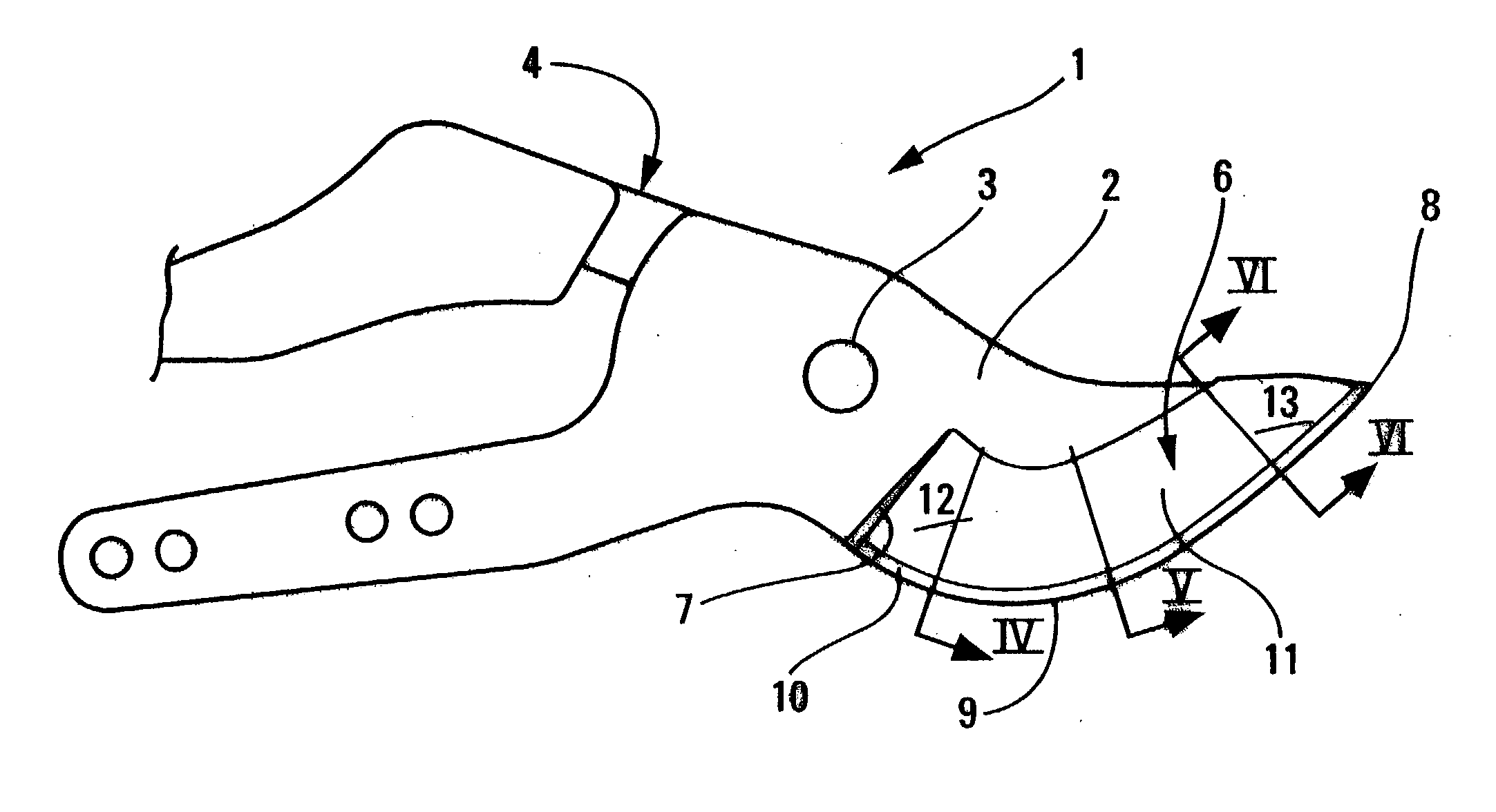
[0017] In the embodiment shown in the figures, the secateurs referenced 1 comprise a cutting blade 2 pivotally mounted about a pin 3 so as to pivot beside a counter-cutting blade 4. Beside the counter-cutting blade 4, the cutting blade 2 has a plane face 5, and on its opposite side it has a beveled face 6 extending longitudinally from a shoulder 7 situated close to the pin 3 to the tip 8 of the cutting blade 2.

[0018] As shown diagrammatically in FIGS. 2 to 6, on its beveled face 6, as seen in cross-section, the cutting blade 2 presents, going away from its cutting edge 9: a first zone 10, also referred to as a "counter-taper", at a first angle A relative to the plane face 5 of the cutting blade 2, and a second zone 11, also referred to as a "taper" making a second angle B with the plane face 5 of the cutting blade 2, when the second angle B is smaller than the first angle A.

[0019] In conventional manner, the first angle A has a value lying in the range about 17.degree. to about 30.d...


PUM


Abstract

The beveled face of the cutting blade presents, in cross-section and going from its cutting edge: a first zone making a first angle with the plane face of the cutting blade; and a second zone making a second angle with the plane face of the cutting blade, the second angle being smaller than the first angle. The second angle has a minimum value in the region of the cutting blade close to the shoulder and a maximum value in a region of the cutting blade close to the tip of the cutting blade.

Description

[0001] The present invention relates to pruning "shears" or "secateurs" comprising in conventional known manner, a cutting blade mounted to pivot about a pin so as to pivot beside a counter-cutting blade, the cutting blade presenting a plane face beside the counter-cutting blade and a beveled face on its other side extending longitudinally from a shoulder situated close to the pin to the tip of the cutting blade, the beveled face of the cutting blade presenting, in cross-section and going away from its cutting edge, a first zone making a first angle with the plane face of the cutting blade, and a second zone making a second angle with the plane face of the cutting blade, the second angle being smaller than the first angle.[0002] In conventional manner, the beveled face is made by machining a plane blank. The first angle and the second angle have values that are constant.[0003] Secateurs of that type generally give satisfaction to their users.[0004] Nevertheless, it is found that the...

Claims


Application Information

Patent Timeline
IPC IPC(8): A01G3/02
CPCA01G3/02
Inventor DEVILLE, ANTOINE
Owner PRUNING SHEARS PRADINES
Learn More