

Conduit Connector
- Summary
- Abstract
- Description
- Claims
- Application Information
AI Technical Summary
Benefits of technology
Problems solved by technology
Method used
Image

Examples
Embodiment Construction
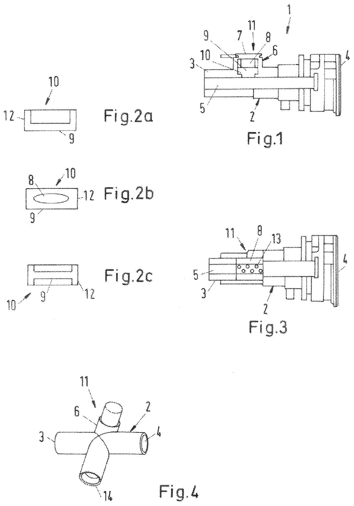
[0024]A conduit connector 1 which has a housing 2 with a first connection geometry 3 and a second connection geometry 4 is shown in FIG. 1. In the housing 2, a channel 5 is formed between the first connection geometry 3 and the second connection geometry 4. In this case, the first connection geometry 3 is configured as an insert connector and the second connection geometry 4 is configured as a connector receiver. A projection 6 which protrudes outwardly from the housing 2 is formed in the region of the first connection geometry 3. In this case, a through-passage is formed in the housing 2 between the channel 5 and an interior of the projection 6.
[0025]The projection 6 and / or the chamber 8 is closed outwardly by a cover 7 which, in particular, is welded and thus is pressure-tight. Thus a chamber 8 which is connected to the channel 5 at least in a pressure-transmitting manner via the through-passage is formed in the interior of the projection 6.
[0026]A penetration of liquid from the c...
PUM
 Abstract
Description
Claims
Application Information