

Part of spinning machine
A technology of textile machines and components, applied in the direction of textiles and papermaking, knitting, mechanical equipment, etc.
- Summary
- Abstract
- Description
- Claims
- Application Information
AI Technical Summary
Problems solved by technology
Method used
Image

Examples
Embodiment Construction
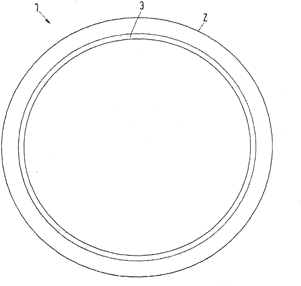
[0020] figure 1 A cross-section of shaft 1 is shown schematically. Here, the shaft 1 has a casing 2 . The reinforcing element 3 is arranged and fastened in the region of the inner diameter of the enclosure 2 .
[0021] A shaft 1 of this type can be manufactured in different types and ways. One possibility should be described below. First, the auxiliary core is introduced into the elastic cylindrical body (for example a hose). This stabilizes the elastic cylinder. In a next step the unidirectional fabric containing the reinforcing fibers is wrapped around the elastic cylinder. The fabric can, for example, contain carbon fiber-reinforced plastic. The unidirectional fabric is then impregnated with adhesive. The adhesive can be designed, for example, to be cold-cured. This makes it possible to carry out the production of the shaft 1 at a predetermined temperature close to room temperature, ie for example 20-22°C. The auxiliary core is then introduced into the casing 2 of ...
PUM
 Abstract
Description
Claims
Application Information