This helps you quickly interpret patents by identifying the three key elements:
Problems solved by technology
Method used
Benefits of technology
Benefits of technology
The patent text describes a system that reduces the risk of the vehicle's steering wheel over-reacting when it turns, by controlling the vehicle's height. This is achieved by using hydraulic cylinders to increase the vehicle's stability and prevent the wheel from getting too far out. This results in a better driving experience for the occupants of the vehicle.
Problems solved by technology
In this case, when all the spring constant change valves are closed to set the front wheel rate and the rear wheel rate to large values, the rear wheel rate may become excessively large.
Then, for example, the rear roll stiffness becomes larger than the front roll stiffness (that is, the rear roll stiffness distribution, or the roll stiffness distribution on the rear wheels side becomes larger than 50%), and thus the steer characteristic of the vehicle may have tendency to oversteer when the vehicle turns.
Method used
Image
Click on the blue label to locate the original text in one second.
Reading with bidirectional positioning of images and text.
Examples
first modified embodiment
[0200]For example, the present invention may be executed in a manner of a first modified embodiment shown in FIG. 8.
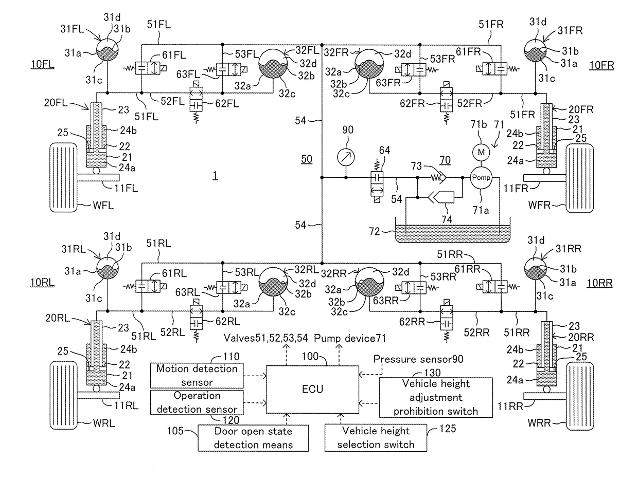
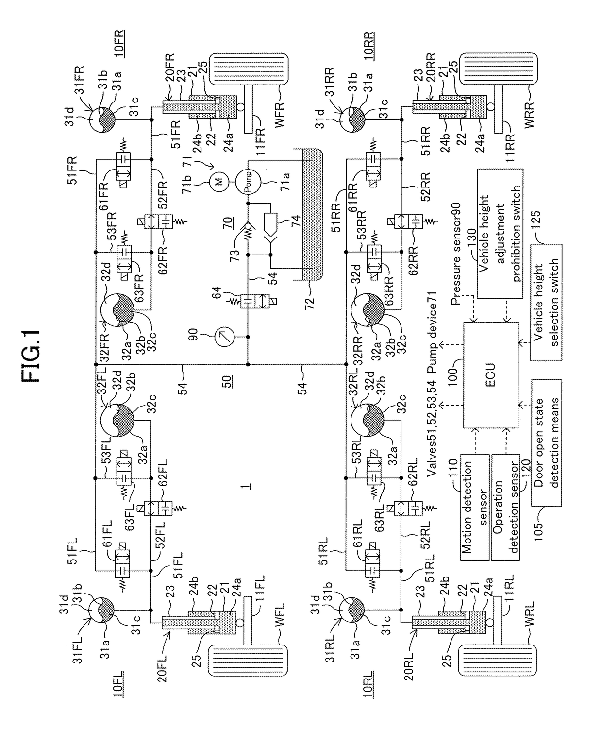
[0201]The front roll stiffness distribution and the rear roll stiffness distribution (i.e., the roll stiffness distribution on the rear wheels WRL, WRR side) actually have a certain correlation with a ratio between the oil pressure of the front wheel side oil hydraulic cylinders 20FL, 20FR and the oil pressure of the rear wheel side oil hydraulic cylinders 20RL, 20RR. That is, a rear wheel side oil pressure ratio, which is the value obtained by dividing the oil pressure of the oil pressure of the rear wheel side oil hydraulic cylinders 20RL, 20RR by the oil pressure of the front wheel side oil hydraulic cylinders 20FL, 20FR, is more than or equal to a predetermined ratio threshold, the rear roll stiffness distribution may become excessively large value.
[0202]The oil pressure threshold Thop of this modified embodiment is set as the oil pressure of the rear wheel side oi...
second modified embodiment
[0212]The present invention may be executed in the manner of a second modified embodiment shown in FIG. 9.
[0213]In the second modified embodiment, the suspension system 1 is configured so that the ECU 100 can execute the wheel rate switching control during the execution of the automatic vehicle height control.
[0214]That is, when the valve switching condition at high pressure is satisfied under the state where the automatic vehicle height control is executed, the ECU 100 executes the specific valve control and stops the automatic vehicle height control.
[0215]The flowchart of FIG. 9 is the same as the flowchart of FIG. 5 except steps 901, 902, 903, 909, 910, 915, and 916.
[0216]First of all, in step 901 the ECU 100 determines whether or not at least one of the luggage door and the side doors is in the opened state at the current time.
[0217]When determining Yes in step 901, the ECU 100 proceeds to step 914.
[0218]Further, the ECU 100 that has finished the processing of step 914 temporari...
PUM
Abstract
A valve control device is configured to execute a specific valve control when a valve switching condition at high pressure is satisfied. The specific valve control switches the spring constant change valves for front wheel to a blocking state and switches a spring constant change valves for rear wheel to a communication permission state. The valve switching condition at high pressure is satisfied when oil pressure of hydraulic oil of rear wheel side oil hydraulic cylinders, which is detected by rear wheel side oil pressure detection means, is more than or equal to a predetermined oil pressure threshold and the traveling state determination means determines that a vehicle is in a predetermined traveling state.
Description
BACKGROUND OF THE INVENTION1. Field of the Invention[0001]The present invention relates to a suspension system capable of adjusting vehicle height using an oil hydraulic cylinder provided between a vehicle body and wheels.2. Description of the Related Art[0002]The suspension system disclosed in Japanese Unexamined Patent Application Publication No. 2008-168861 is provided with four oil hydraulic cylinders each of which corresponds to one of left and right front wheels and left and right wheels, respectively. Each of the oil hydraulic cylinders is connected to a hydraulic oil supply / discharge device via corresponding one of individual control passages.[0003]An individual control valve is provided in each of the individual control passages. Each individual control valve opens and closes the corresponding one of the individual control passages.[0004]When hydraulic oil is supplied to each of the oil hydraulic cylinders from the hydraulic oil supply / discharge device by controlling the in...
Claims
Application Information
Patent Timeline
Application Date:The date an application was filed.
Publication Date:The date a patent or application was officially published.
First Publication Date:The earliest publication date of a patent with the same application number.
Issue Date:Publication date of the patent grant document.
PCT Entry Date:The Entry date of PCT National Phase.
Estimated Expiry Date:The statutory expiry date of a patent right according to the Patent Law, and it is the longest term of protection that the patent right can achieve without the termination of the patent right due to other reasons(Term extension factor has been taken into account ).
Invalid Date:Actual expiry date is based on effective date or publication date of legal transaction data of invalid patent.

