
Method and system for diagnosis of plant

a plant and diagnosis system technology, applied in the field of plant diagnosis system, can solve the problems of not being able to disclose, generally impossible to incorporate, and difficulty in maintenance operation of the diagnosis computer 3, and achieve the effect of avoiding the loss of the diagnosis system

Inactive Publication Date: 2003-08-14
KK TOSHIBA
View PDF33 Cites 12 Cited by
  • Summary
  • Abstract
  • Description
  • Claims
  • Application Information

AI Technical Summary

Benefits of technology

[0016] Another object of the present invention is to provide a user-friendly plant diagnosis method and system which allows a user to judge the necessity of a secondary diagnosis on the user's initiative.
[0017] A further object of the present invention is to provide a plant diagnosis method and system which unnecessitates a diagnosis computer or a terminal thereof in a user organization to allow a reduction in initial cost and / or maintenance cost of an entire plant system.
[0018] Another object of the present invention is to provide a plant diagnosis method and system which provides a user organization with a larger latitude of plant system designing and also with various plant diagnosis services, which are accurate, of high added value and can be quickly available from a diagnoser organization.
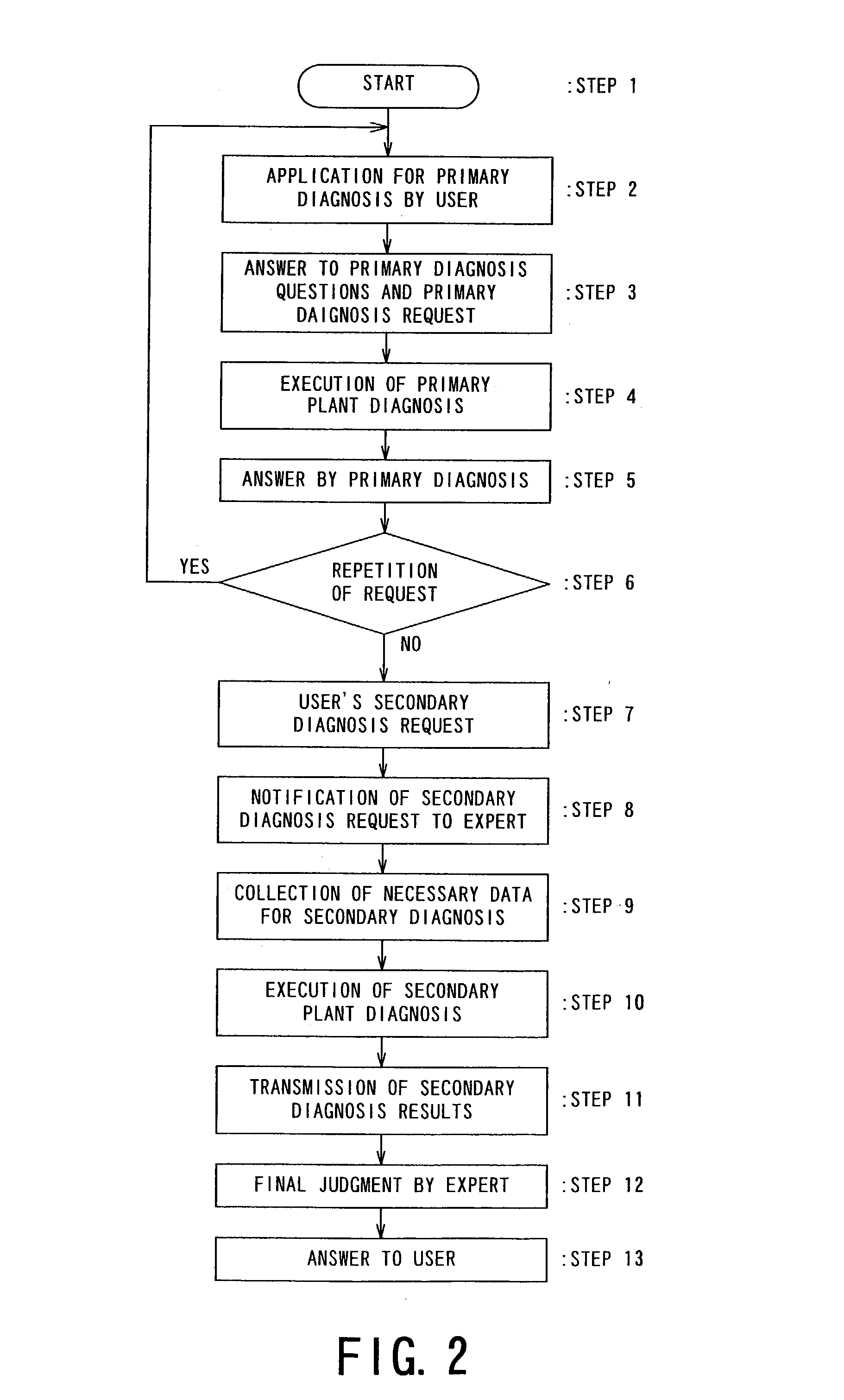
[0019] Still another object of the present invention is to provide a flexible and highly reliable plant diagnosis method and system which allows an on-line primary diagnosis, and a secondary diagnosis that is available by switching from the primary diagnosis and performed while relying on a plant diagnosis expert via a tele-communication network, thus allowing intensive, accurate and quickly reliable plant diagnosis.

Problems solved by technology

Further, the publications also fail to disclose a plant diagnosis system convenient or friendly to a user (organization) (i.e., a plant operating organization or company) so as to allow the user such repetitive plant diagnosis which can be conveniently relied on by the user on the user's initiative without hesitation and without a limit in number of plant diagnosis.
It is generally impossible to incorporate, in such a plant diagnosis system, various diagnostic algorithm corresponding to possibly occurring abnormal phenomenon in prediction thereof at the time of installation of the system.
Moreover, the maintenance operation of a diagnosis computer 3 is rather complicated and time-consuming regardless of a low frequency of use of the diagnosis computer 3.
This results in an increase in running cost of the entire plant system including such a diagnosis system 1.
Further, for a conventional plant diagnosis system, there can occur a new abnormal phenomenon which does not allow the diagnosis system to identify the nature of the abnormality of plant machinery.
In case where such an order is not convenient, the user can possibly hesitate the order, and such a situation can be expected that a substantial time lapses until an actual order to result in a serious plant condition before the action of the diagnoser organization.
In the case of requiring an urgent plant diagnosis, the plant diagnosis has to be performed in the presence at the plant of a plurality of experts from such a diagnoser organization, so that the diagnosis cost is liable to be expensive relative to the actual operation.

Method used

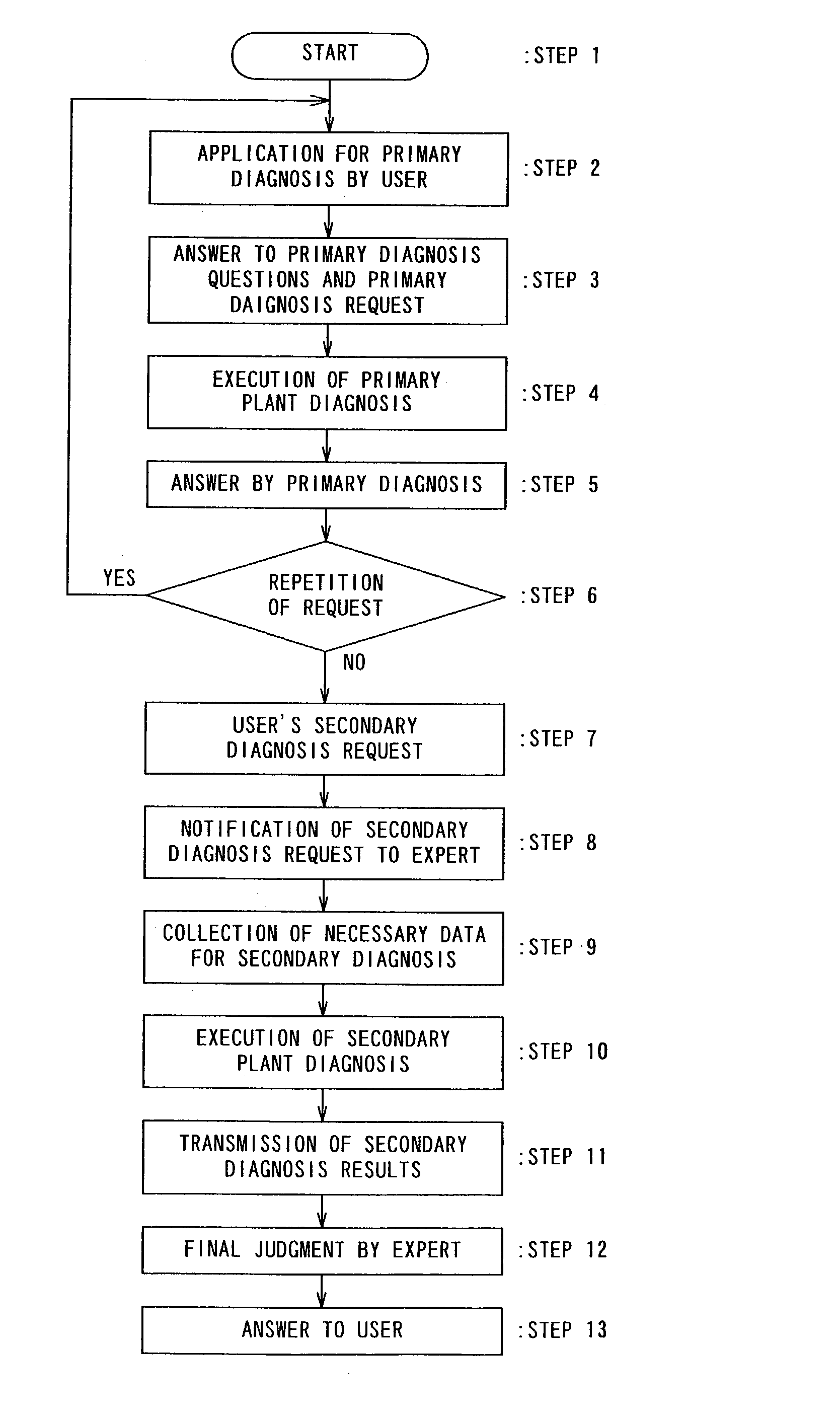

Image

  • Method and system for diagnosis of plant
  • Method and system for diagnosis of plant
  • Method and system for diagnosis of plant

Examples


Embodiment Construction

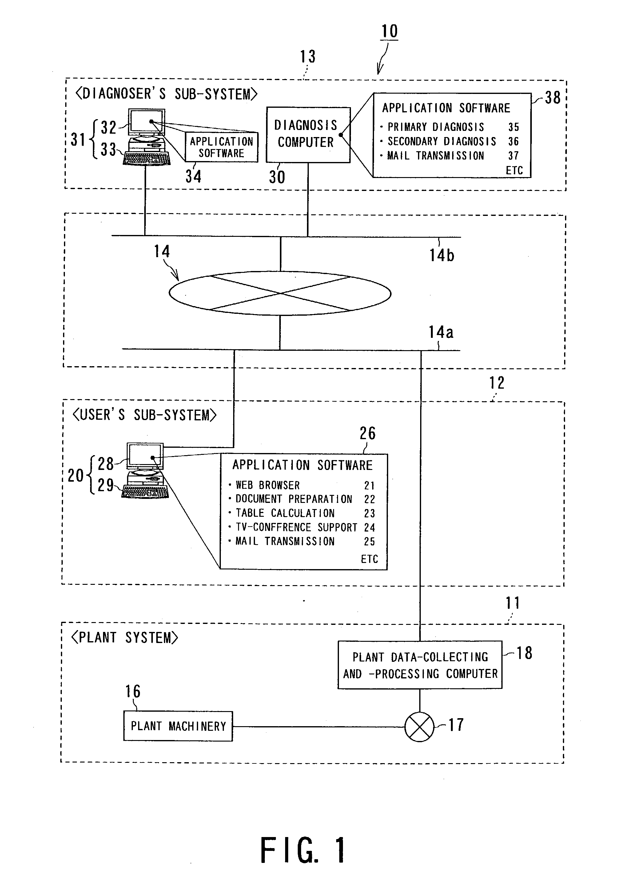
[0044] FIG. 1 is a block diagram illustrating an embodiment of the plant diagnosis system according to the present invention. Referring to FIG. 1, there is illustrated a plant diagnosis system 10 for judging the presence or absence of abnormality and identifying the nature of abnormality, if any, of a plant of various types, inclusive of various power plants, such as a steam power plant and an atomic power plant, a chemical process plant, and a steel production plant, by inputting various state variables of the plant for performing the judgment.

[0045] The plant diagnosis system 10 includes a user's unit (or sub-system) 12 disposed on the side of a plant system 11, such as a steam power plant, and a diagnoser's unit (or sub-system) 13 disposed in a diagnoser organization, such as a plant maker or a consultant company, which are connected via the (tele-)communication network 14 (including a principally user's side line 14a and a principally diagnoser's side line 14b) so as to allow ex...


PUM


Abstract

A plant diagnosis system friendly to a user (a plant-operating organization) for identifying an abnormality of an objective plant or machinery thereof, is provided. The plant diagnosis system includes a diagnoser's sub-system including a diagnosis computer and a terminal for a diagnosis expert and is connected via a network to a user's sub-system including a terminal for communicating with the diagnoser's sub-system. The plant diagnosis system provides a simple but repetitively available primary diagnosis and a detailed secondary diagnosis including the expert's judgement, which are selectively available on the user's initiative. The diagnosis computer receives a diagnosis request and plant state variables of the plant or machinery and executes the primary diagnosis and a part of the secondary diagnosis based on the plant state valuables.

Description

FIELD OF THE INVENTION AND RELATED ART[0001] The present invention relates to a method and a system for diagnosis of a plant, i.e., an apparatus or apparatus system for carrying on an industrial business, or machinery organizing the plant, as an object of diagnosis, by receiving variables representing such an objective plant or plant machinery.[0002] Various types of plants, inclusive of a steam power plant, an atomic energy power plant, a combined cycle power plant, a chemical plant and a steel production plant, are equipped with their own plant diagnosis system including various sensors for detecting physical state variables (plant state(--representing)variables), such as a temperature, a pressure, a flow rate and vibration data during operation of the plant, and a diagnosis computer (i.e., a computer for diagnosis) receiving the detected plant state variables to diagnose the objective plant or plant machinery with respect to the presence or absence of abnormality or identifying t...

Claims


Application Information

Patent Timeline
Patent Type & Authority Applications(United States)
IPC IPC(8): G01M99/00G05B23/02G06Q50/06G06Q50/00G06Q50/10G07C3/00
CPCG07C3/00G05B23/0216
Inventor OKAZAKI, MITSUYOSHIASATSU, SEIICHIWATANABE, SHUNZO
Owner KK TOSHIBA
Learn More