
Fuel injection valve with a damping element

a technology of damping element and fuel injection valve, which is applied in the direction of spray nozzles, machines/engines, mechanical equipment, etc., can solve the problems of disturbing noise emissions during the operation of fuel injectors and adversely affecting operating safety

Inactive Publication Date: 2003-08-21
ROBERT BOSCH GMBH
View PDF12 Cites 7 Cited by
  • Summary
  • Abstract
  • Description
  • Claims
  • Application Information

AI Technical Summary

Benefits of technology

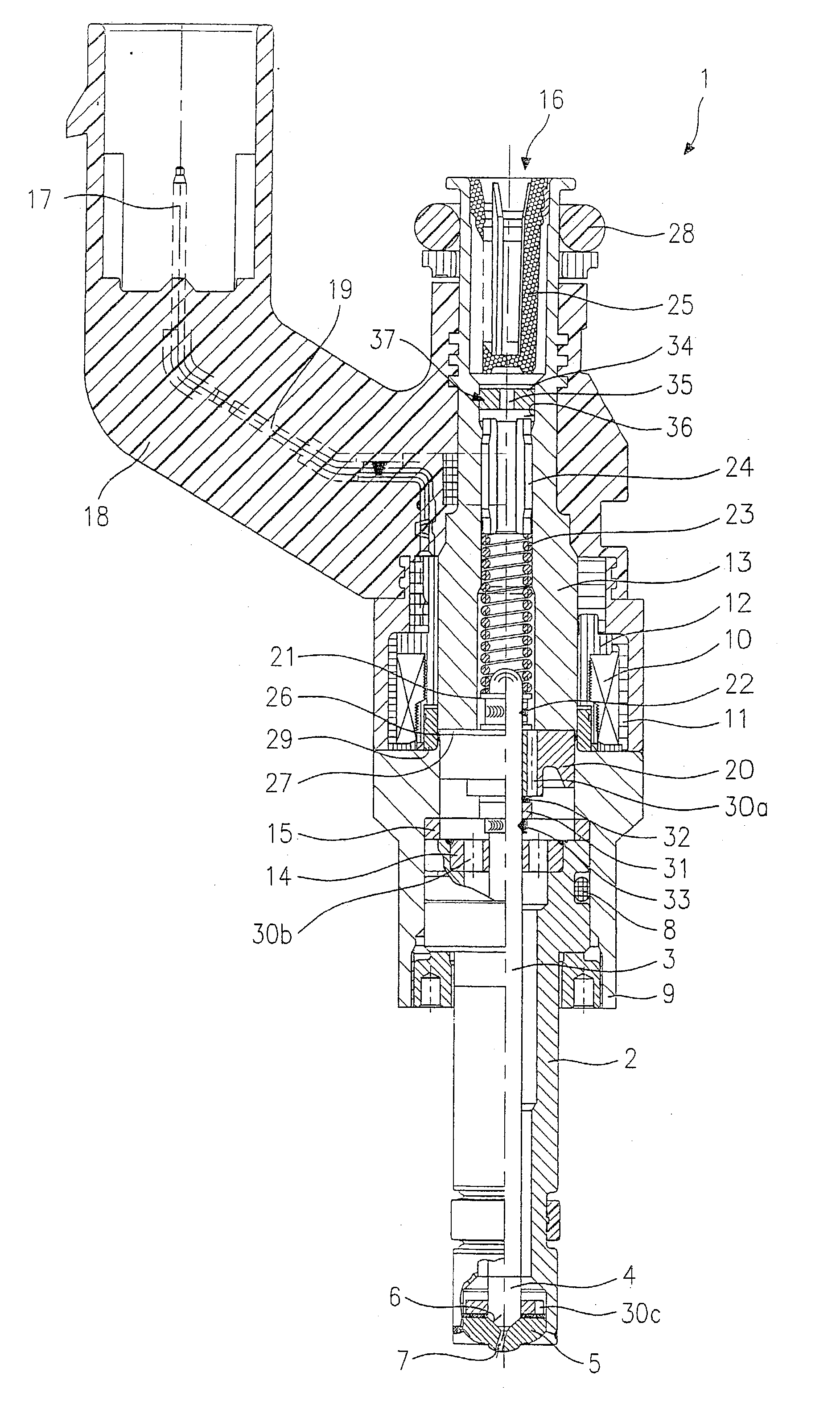
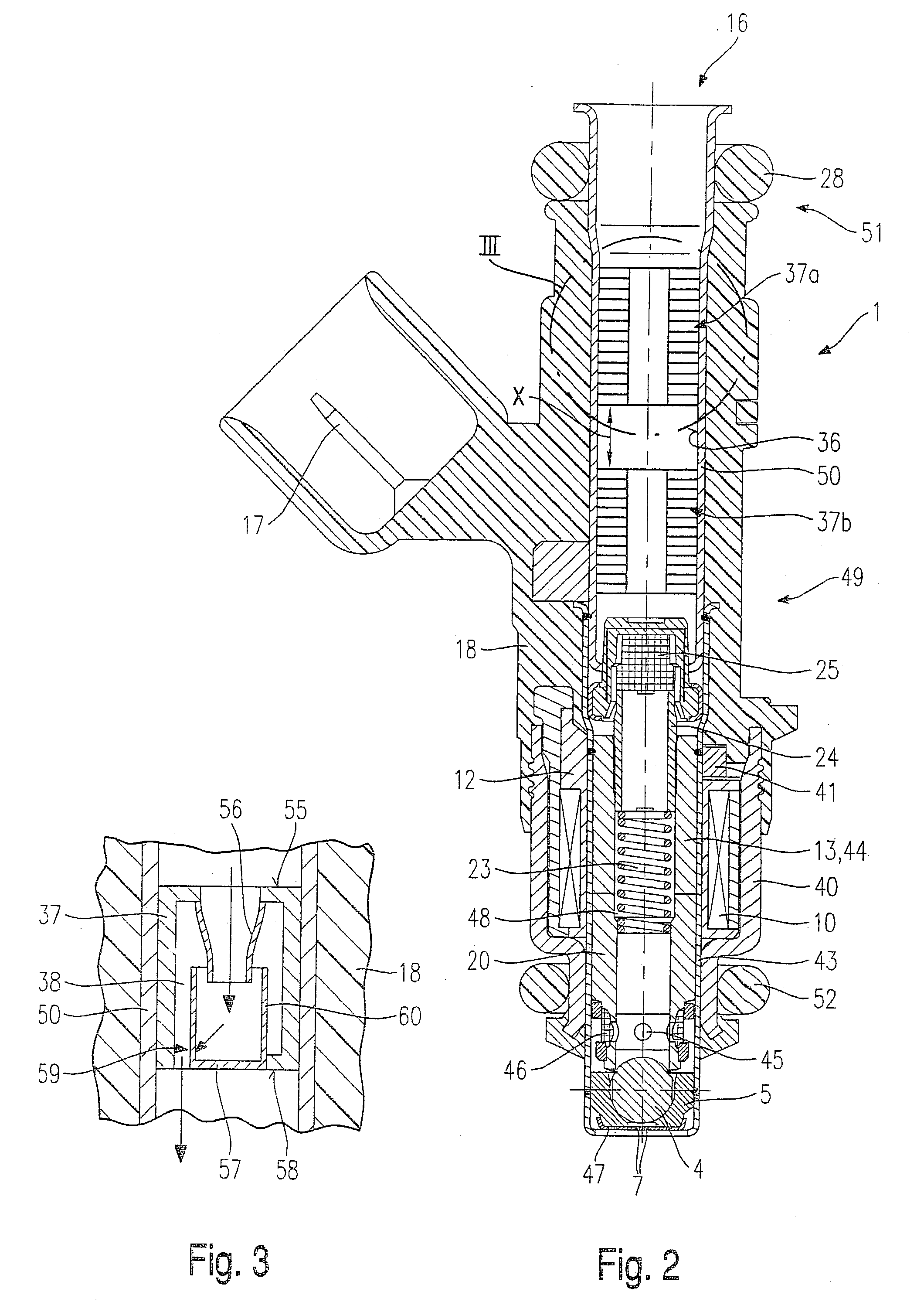
[0024] According to the present invention, a screen 34, which is provided with a bore 35, is disposed in an opening 36 of inner pole 13. Screen 34 is situated between filter element 25 and adjusting sleeve 24 downstream from filter element 25, thereby holding back impurities in the fuel flowing through filter element 25 and screen 34 as well, so that no clogging occurs at bore 35 of screen 34.
[0025] With the aid of screen 34, it is possible to prevent pressure pulsations from occurring during the operation of fuel injector 1. The pressure pulsations are caused, for instance, by the cyclical opening and closing of fuel injector 1, thereby subsequently causing noise problems in the distributor line (not shown further). The severing of plug-in connections between individual components due to excited oscillations may also be prevented by the damping of pressure pulsations.
[0027] Bore 35 of screen 34 is dimensioned such that the pressure pulsations are effectively damped, but the fuel flow through fuel injector 1 is not restricted in the process. The stronger the damping of the pressure pulsations, the lower the resonance in the fuel-distributor line and the noise emissions it causes.

Problems solved by technology

Disadvantageous in the fuel injector known from DE 196 26 576 A1, in particular, is that pressure pulsations which are predominantly caused by the cyclical opening and closing of the fuel injector, are transmitted undamped to other parts of the fuel injection system, such as to the fuel distributor line, thereby causing resonances that lead to disturbing noise emissions during operation of the fuel injector.
Because of resonances, it is also possible that, due to vibrations, connections between components are severed, which may cause error functions of the fuel injection system and even the internal combustion engine, thereby adversely affecting operating safety.

Method used


Image

  • Fuel injection valve with a damping element
  • Fuel injection valve with a damping element
  • Fuel injection valve with a damping element

Examples


Embodiment Construction

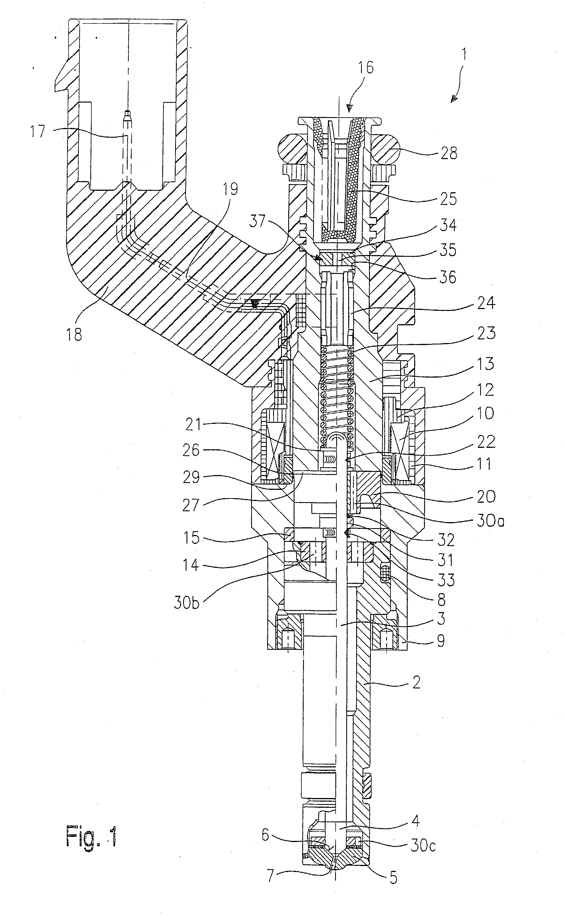
[0016] FIG. 1 shows a part-sectional representation of a first exemplary embodiment of a fuel injector 1 according to the present invention. It is in the form of a fuel injector 1 for fuel-injection systems of mixture-compressing internal combustion engines having external ignition. Fuel injector 1 is suited for the direct injection of fuel into a combustion chamber (not shown) of an internal combustion engine.

[0017] Fuel injector 1 is composed of a nozzle body 2 in which a valve needle 3 is positioned. Valve needle 3 is in operative connection with a valve-closure member 4, which cooperates with a valve-seat surface 6 disposed on a valve-seat member 5 to form a sealing seat. In the exemplary embodiment, fuel injector 1 is an inwardly opening fuel injector 1 which has a spray-discharge orifice 7.

[0018] A seal 8 seals nozzle body 2 from an outer pole 9 of a magnetic coil 10. Magnetic coil 10 is encapsulated in a coil housing 11 and wound on a coil brace 12, which rests against an inn...


PUM


Abstract

A fuel injector (1) is provided with a magnetic coil (10) which cooperates with an armature (20) acted upon by a restoring spring (23), the armature forming an axially movable valve part with a valve needle (3). A valve-closure member (4) which forms a sealing seat with a valve-seat member (5) is provided at the valve needle (3). At least one damping element (37) is disposed in an opening (36) of the fuel injector (1) through which fuel flows.

Description

BACKGROUND INFORMATION[0001] The present invention is based on a fuel injector of the type set forth in the main claim.[0002] As an example, from DE 196 26 576 A1 an electromagnetically actuable fuel injector is known, in which, for the electromagnetic actuation, an armature cooperates with an electrically energizable magnetic coil, and the lift of the armature is transmitted to a valve-closure member via a valve needle. The valve-closure member cooperates with a valve-seat surface to form a sealing seat. A plurality of fuel channels is provided in the armature. The armature is reset by a resetting spring.[0003] Disadvantageous in the fuel injector known from DE 196 26 576 A1, in particular, is that pressure pulsations which are predominantly caused by the cyclical opening and closing of the fuel injector, are transmitted undamped to other parts of the fuel injection system, such as to the fuel distributor line, thereby causing resonances that lead to disturbing noise emissions duri...

Claims


Application Information

Patent Timeline
IPC IPC(8): F02B75/12F02M61/10F02M51/06F02M51/08F02M55/04F02M61/12F02M61/16F02M61/18F02M63/00
CPCF02B2075/125Y10S239/90F02M51/0671F02M51/0685F02M55/04F02M61/12F02M61/16F02M61/166F02M61/168F02M61/1806F02M2200/306F02M2200/31F02M2200/315F02M2200/50F02M2200/9015F02M2200/903F02M2200/9053Y02T10/123F02M51/0667Y02T10/12
Inventor REITER, FERDINANDFISCHER, ULRICHTHOMMES, FRANZ
Owner ROBERT BOSCH GMBH
Learn More