Installation device

a technology of installation device and installation plate, which is applied in the direction ofauxillary welding device, soldering apparatus, manufacturing tools, etc., can solve the problems of complex cleaning device, difficult shortening the total time of a series of operations, and difficult shortening the tact tim

Inactive Publication Date: 2003-09-04
TORAY ENG CO LTD +1
View PDF1 Cites 10 Cited by
  • Summary
  • Abstract
  • Description
  • Claims
  • Application Information

AI Technical Summary

Problems solved by technology

Although there is a method for cleaning a bonding surface at the substantially same place as a place for bonding, in such a case, because the bonding must be carried out after the cleaning and both operations must be carried out in series, it is difficult to shorten the total time for a series of operations.
Therefore, in a manufacturing process where chips and substrates are conveyed continuously and a mass production is required, it becomes difficult to shorten the tact time.
Further, although it is possible to clean the bonding surface of a chip and the bonding surface of a substrate at a condition before mounting where both objects are held to face each other, because the respective surfaces facing in the directions opposite to each other must be cleaned, the cleaning device becomes complicated.
Moreover, similarly to the above-described method, since the cleaning and the bonding must be carried out in series, it is difficult to shorten the total time for a series of operations.
Further, in a case where the surface irregularity is small (the flatness is high), pressing for bonding also becomes unnecessary.
However, in such a room-temperature bonding, or even in a case where the cleaning by means of the irradiation of the energy wave or energy particle beam is carried out, when the irradiation of the energy wave or energy particle beam and the bonding are carried out at a substantially same place, similarly to in the aforementioned case, it becomes difficult to shorten the total time for a series of operations, and it becomes difficult to shorten the tact time in a mass production.
Further, since the bonding surface cleaned by the irradiation of the energy wave or energy particle beam becomes a highly cleaned bonding surface, in order to maintain the cleaned state until a time immediately before bonding, the handling of the object after cleaning becomes difficult, and a particular device is required.

Method used


Image

  • Installation device
  • Installation device
  • Installation device

Examples


Embodiment Construction

[0031] Hereinafter, desirable embodiments of the present invention will be explained referring to figures.

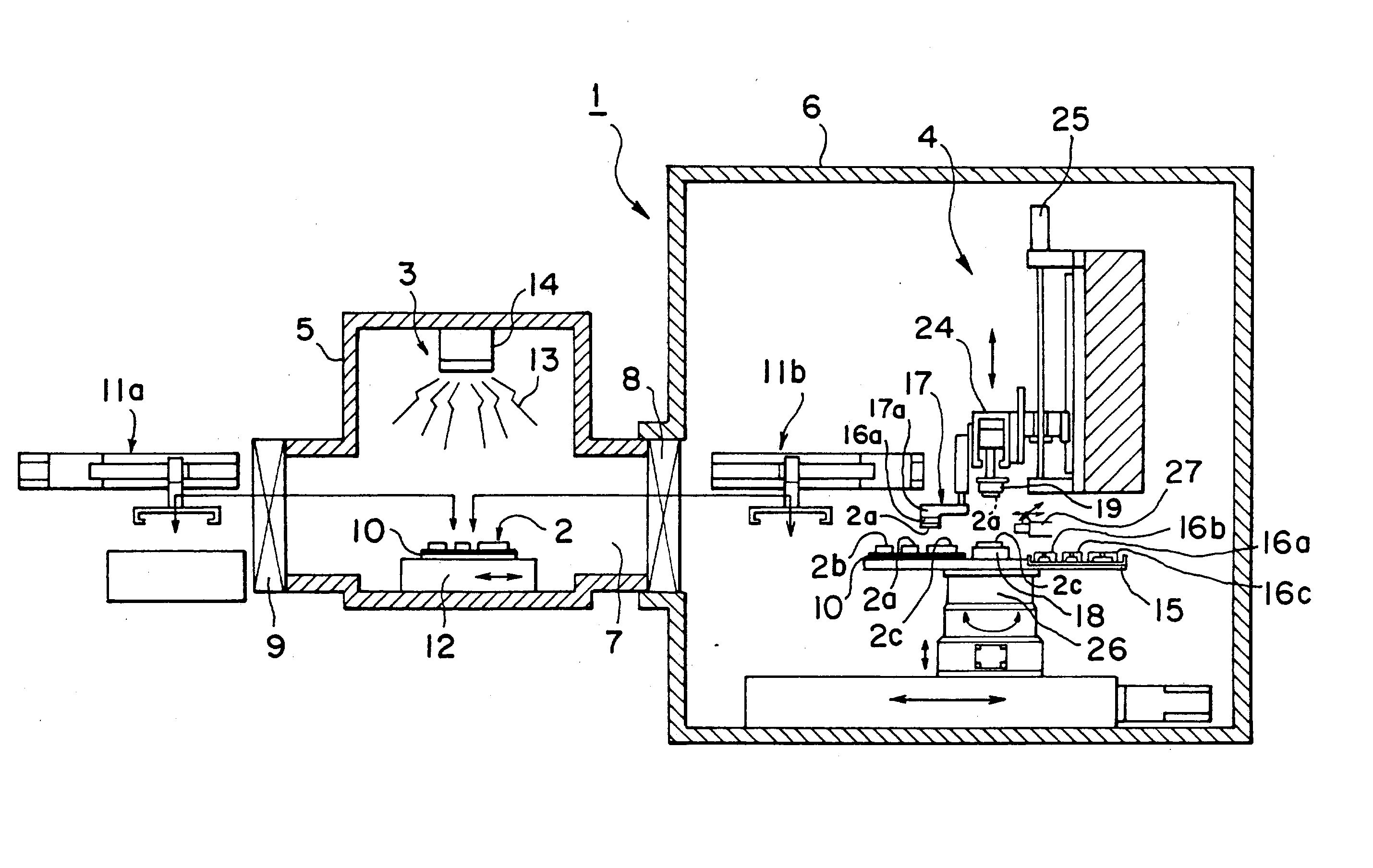
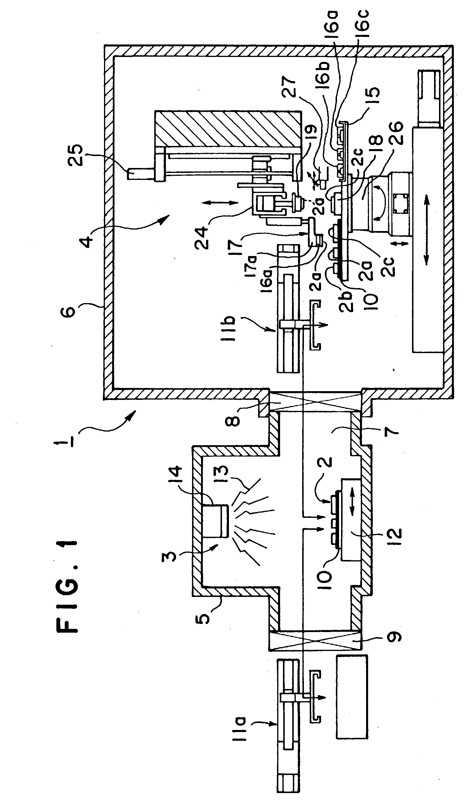
[0032] FIG. 1 shows a mounting apparatus according to an embodiment of the present invention. A mounting apparatus 1 comprises a cleaning part 3 for objects to be bonded 2, and a bonding part 4 for bonding objects 2 to each other, and in this embodiment, the cleaning part 3 is installed in a cleaning chamber 5 and the bonding part 4 is installed in a bonding chamber 6. Both chambers 5 and 6 are connected to each other via a conveying path 7 so that objects 2 can be conveyed between both chambers, a shutter means 8 capable of being opened and closed is provided between both chambers 5 and 6, and a shutter means 9 is provided also at the entrance side of the cleaning chamber 5.

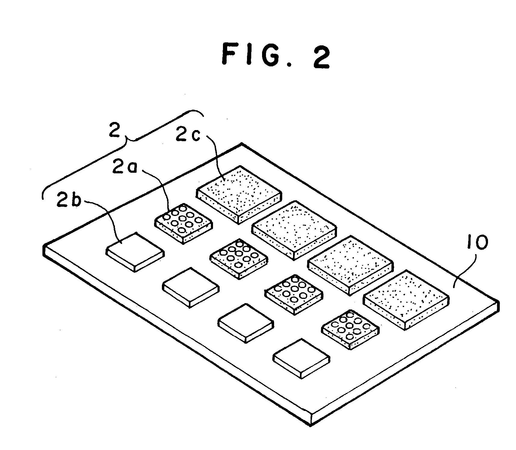
[0033] As the objects 2, in this embodiment, for example, as shown in FIG. 2, chips 2a and chips 2b are prepared as first objects and substrates 2c are prepared as second objects, a first object (a chip) 2a ...


PUM

PropertyMeasurementUnit
pressureaaaaaaaaaa
energyaaaaaaaaaa
temperatureaaaaaaaaaa

Abstract

A mounting apparatus for bonding objects to each other, comprising a cleaning part (3) for cleaning at least the bonding surfaces of first objects (2a, 2b) and a bonding part (4) for bonding the cleaned first objects (2a, 2b) to a second object (2c), wherein both parts are connected to each other so that the objects can be conveyed between both parts, and an inverting mechanism (17) for turning over the first objects (2a, 2b) without touching the cleaned bonding surfaces is provided in the bonding part, whereby the cleaning of the bonding surfaces can be carried out efficiently, and a total time for a series of operations ranging from the cleaning to the completion of bonding can be shortened remarkably.

Description

[0001] The present invention relates to a mounting apparatus for bonding objects such as chips to each other, and specifically to a mounting apparatus having a process for cleaning bonding surfaces.BACKGROUND ART OF THE INVENTION[0002] For example, for mounting a chip onto a substrate, a mounting method is known wherein the bonding surface of the chip, as the case may be, the bonding surface of the substrate, is cleaned in various manners, and thereafter, the chip with the cleaned bonding. surface is bonded to the substrate. Usually, a substrate is fixed at a predetermined position on a substrate stage, and a single or a plurality of chips adjusted in positional relationship relative to the substrate are mounted on the substrate.[0003] Although there is a method for cleaning a bonding surface at the substantially same place as a place for bonding, in such a case, because the bonding must be carried out after the cleaning and both operations must be carried out in series, it is diffi...

Claims


Application Information

Patent Timeline
Patent Type & Authority Applications(United States)
IPC IPC(8): B23K1/20H05K3/34H01L21/00H01L21/60
CPCB23K1/20H01L24/75H01L21/67144H01L2924/12042H01L2924/00H01L21/60
Inventor SUGA, TADATOMOYAMAGUCHI, AKIRO
Owner TORAY ENG CO LTD
Why Eureka
Try Eureka