Magnetic field detection device

a magnetic field and detection device technology, applied in the direction of burglar alarm mechanical actuation, burglar alarm by hand-portable object removal, instruments, etc., can solve the problems of increasing the cost, not being able to selectively detect the aimed signal component of the prior magnetic sensor described above,

Inactive Publication Date: 2003-09-04
AICHI MICRO INTELLIGENT
View PDF4 Cites 19 Cited by
  • Summary
  • Abstract
  • Description
  • Claims
  • Application Information

AI Technical Summary

Benefits of technology

[0011] The first invention, a magnetic field detection device, constituted as described above, imparts a frequency response to the negative feedback signal through the frequency response affording means provided in the negative feedback circuit which connects the output terminal of the magnetic field detection device with the negative feedback coil, thereby resulting in a magnetic field detection device which allows for the detection of the desired magnetic signal in the desired frequency domain selectively and accurately with a high level of sensitivity and low cost.
[0012] The second invention, a magnetic field detection device, constituted as described above, in the first invention, comprises said filter, which forms said frequency response affording means, and serves to afford a frequency characteristics on the magnetic field detection device by zeroing the internal magnetic field of said magneto-impedance element, which allows the magnetic signal components in the desired frequency domain to be detected selectively, thereby resulting in a magnetic field detection device that can detect magnetic signal components in the desired frequency domain accurately with a high level of sensitivity and low cost.

Problems solved by technology

Prior magnetic sensors described above can not detect selectively the aimed signal component from extraneous components.
However such filters require current amplifier, so the scale of the detecting system becomes large and results in increase of the cost.

Method used


Image

  • Magnetic field detection device
  • Magnetic field detection device
  • Magnetic field detection device

Examples


Embodiment Construction

[0028] The preferred embodiments of the present invention are explained below with use of the attached figures.

The First Preferred Embodiment

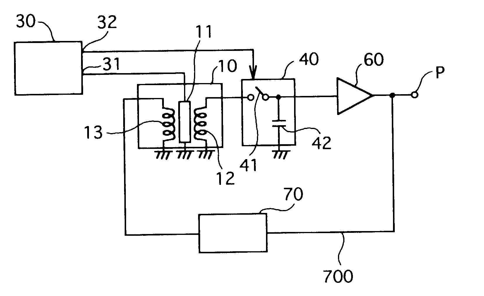
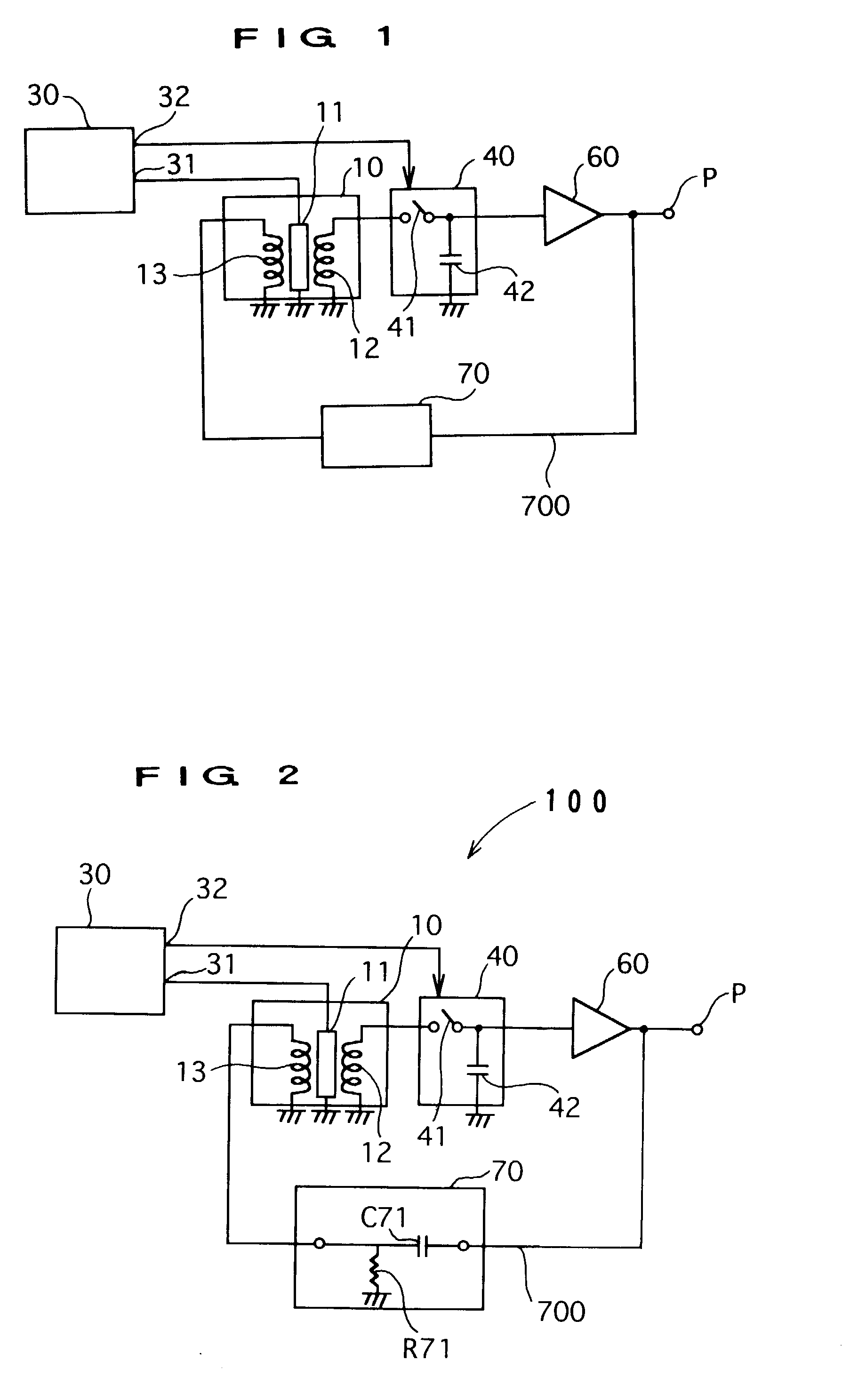
[0029] The first preferred embodiment of the magnetic field detection device, as shown in FIG. 1, consists of a magneto-impedance (MI) element 11, whose impedance changes in response to external magnetic fields, a detector coil 12 and negative feedback coil 13 which is wound around MI element 11, and a filter 70 which plays a role as the frequency characteristics affording means or frequency response imparting means which, by means of affording or imparting a frequency characteristics to the negative feedback signal provided in the negative feedback circuit 700 which connects the output terminal of the magnetic field detection device and negative feedback coil 13, allows the magnetic signal component of a frequency characteristics or response in which only the signal components in the negative feedback signal's frequency domain have been substa...


PUM


Abstract

The present invention is a magnetic field detection device that makes use of a frequency characteristic affording circuit in order to selectively detect magnetic signals from a frequency domain accurately at a high level of sensitivity. The present invention has a magneto-impedance element, a detector coil and a negative feedback coil which is wound around the magneto-impedance element, and a frequency characteristic affording circuit which affords a frequency characteristics on the negative feedback signal of a negative feedback connecting an output terminal thereof with the negative feedback coil. Using filters as the frequency characteristic affording circuit, the following are possible uses of this magnetic field detection device: a geomagnet detection device for earthquake prediction (using a high-pass filter), a bill validation apparatus for vending machines, etc. (using a low-pass filter), and a magnetic oscillation detection device for a magnetic gate system (using a band-reject filter).

Description

[0001] The present invention relates to a magnetic field detection device which outputs electric signals in response to external magnetic fields.PRIOR ART[0002] Prior magnetic sensors (Japanese Patent Laid-Open 2000-258517), as shown in FIG. 10, comprising a magneto-impedance element 1, whose impedance changes in response to external magnetic fields, a detection coil C, which converts changes in impedance detected through the magneto-impedance element I into electric signals, and a negative feedback coil NC, which can generate a negative feedback magnetic field that cancels the magnetic field around said magneto-impedance element I, offset the external magnetic field by generating a negative feedback magnetic field around magneto-impedance element I with the negative feedback coil NC.[0003] The presence of magnetic fields on Earth range from natural ones caused by geomagnetism to man-made fields. From the viewpoint of frequency, they range from constant magnetic field to high freque...

Claims


Application Information

Patent Timeline
Patent Type & Authority Applications(United States)
IPC IPC(8): G01R33/02
CPCG01R33/02
Inventor SUMI, KAZUMASANAGAO, TOMOHIKOHONKURA, YOSHINOBUMORI, MASAKI
Owner AICHI MICRO INTELLIGENT
Why Eureka
Try Eureka