Fastening device with adjustable fastening surface embedded in cast panel or other products

a technology of fastening device and cast panel, which is applied in the direction of sheet joining, building components, nuts, etc., can solve the problems of no structural or optionally adjustable fastening surface, no means of positioning foam or other barrier, no means of fixing other things such as fixtures, handles, etc., to reduce the effect of reducing the risk of job si

Inactive Publication Date: 2003-09-11
JANEWAY DAVID
View PDF24 Cites 38 Cited by
  • Summary
  • Abstract
  • Description
  • Claims
  • Application Information

AI Technical Summary

Benefits of technology

[0081] a. embodied in the component or device, provides a stable nailing or fixturing surface within or on the surface of a cast panel such as a poured concrete ceiling, floor, or wall, which provides for an improved method of breakback of the form ties, and the fixturing surface of which is adjustable in relationship to other like devices so cast in the same surface, and to the cast surface itself, comprised of a stable, inert, non-metallic, plastic, metallic, weldable, glueable, screwable, material and surface as desired;
[0115] It also allows for temporary use and subsequent removal and simple patching rather than cutting, and leaves no corrodable surfaces to stain the surface or promote spalling where moisture is present. Additionally, the component comprising my invention may if required by affixed as are the prior art anchors by drilling, gluing, otherwise embedding, and the like, but the component, being adjustable, requires less precise placement, less stringent methods, and less trained labour.

Problems solved by technology

The prior art has disadvantages in that:
the break-back of the metal form tie results in panel surface damage and a requirement to patch;
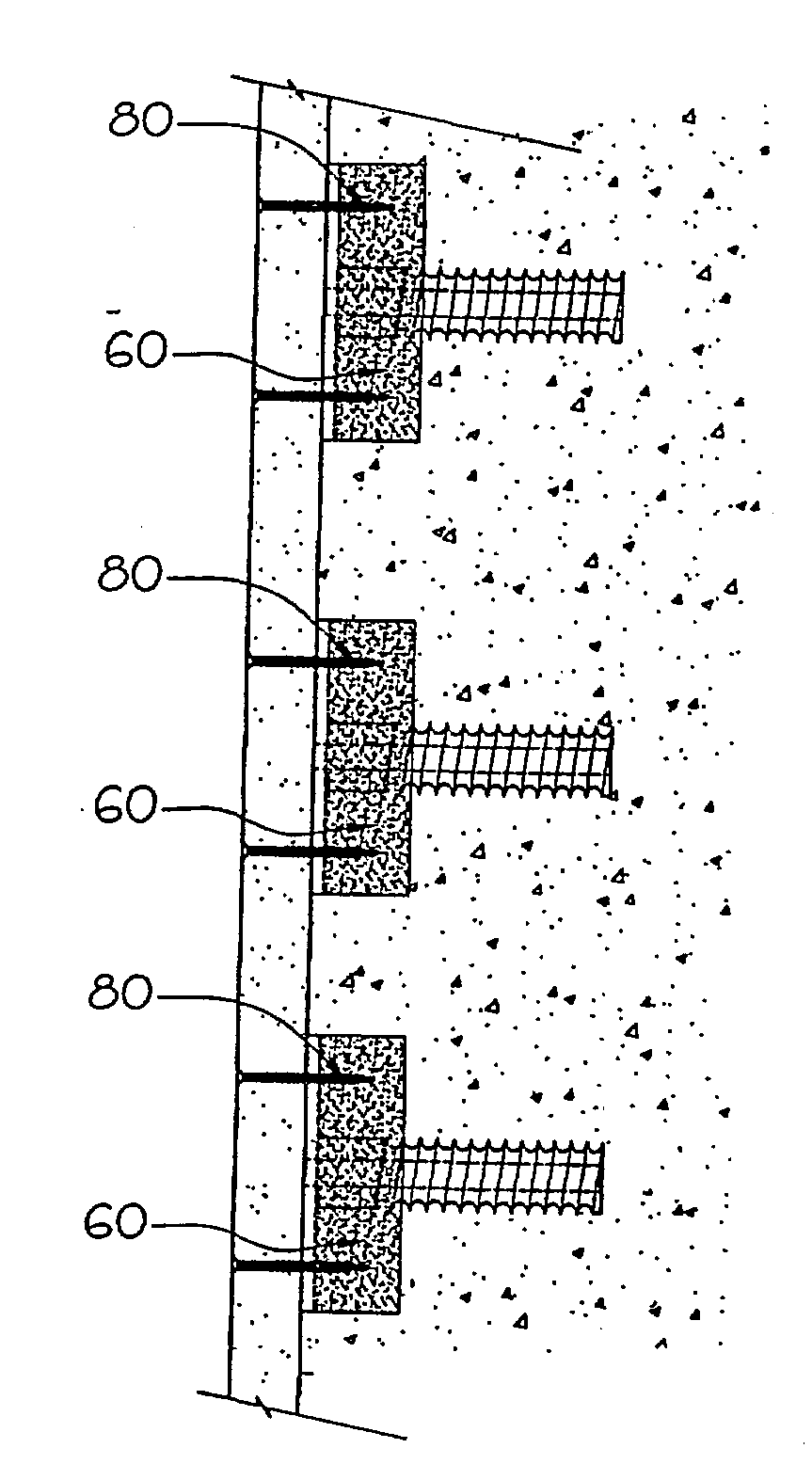
there is no structural or optionally adjustable fastening surface or means for attachment of other things such as fixtures, handles, carriers, and the like, nor any means of positioning a foam or other barrier during (and after) casting of the panel;
the form ties leave protruding ends to be broken back, requiring additional labor and potential damage to the panel or element.
This complicates the engineering and building code considerations due to the structure being considered composite rather than monolithic.
In the field, it is difficult to suspend a barrier within a form without rupture and movement due to head pressures developed by the uneven filling of the divided elements.
This has not become widespread practice due to the difficulty of lacing two forms and up to two layers of insulation together with the tie acting to restrain all elements from moving relative to one another during the pouring and casting steps.
It is difficult and time consuming to line up the hole in the form, the (up to) two foam panels and then close up the forms aligning all the ties with all the holes in the "buttoning up" procedure.
This was further aggravated by the lack of a standard grid matrix that ties and tie holes would be located relative to (and thus the lack of any standard to which foam panels could be produced to fit the grid array of form ties which, when assembled, would pierce the foam layer comprised of the foam panels).
It was also difficult to assure that the insulation panels had not moved out into the concrete void due to all the adjustments required.
Consistent delivery of these required properties in face of the variables involved with the head and impact pressures of fresh concrete pours is difficult to achieve.
Typically, the practice of vibrating walls with a mechanical immersion vibrator after pour but prior to curing is discouraged due to concerns over possible rupture due to damage caused by contact of the vibrator with the foam forms and also due to concerns for the increase in form pressure brought about by liquefying the concrete through vibration.
Concerns for the complete compaction of the concrete are difficult to quantify or visually inspect, given that all exposed surfaces are covered with foam.
Concerns for water-tightness due to lack of vibratory consolidation arise out of and can be attributed to lack of consolidation around the numerous ties required to reinforce the two (foam) face shells.
Nailing surfaces are not adjustable to overcome these site deficiencies.
This prior art system is additionally restricted in its use for a number of reasons; it is practical only on exterior walls where thermal resistance is desired.
The thickness of the exterior shell adds to the overall dimension of the foundation which can effect building lot set backs as well as increasing the total building footprint.
Thicker walls require changes to a number of building details such as width of window and door sills, etc. and adaptations from standard dimension lumber and finished parts, adding significantly to costs.
Code issues see a requirement for interior insulated surfaces to be covered with a fire rated material, such as drywall.
In some jurisdictions, the use of a firewall is restricted due to the plastic ties connecting the two wall surfaces present in common commercially produced ICF systems.
The use below grade in most termite areas is restricted or forbidden due to the foam providing a conduit for the insects to enter the home up the outside of the wall under the finishes.
The system is not in widespread use and the restrictions and problems are not yet documented.
The nailer provided in Martineau is not adjustable.
The drawbacks to this system were the variability of the wood in terms of the ability to hold the nail, the effect of swelling and shrinking of the block within the hardened concrete pocket, rotting and insect attack in some geographic areas, and the inability to quantify the engineering properties of the connection.
The drawbacks are that one cannot drive a nail into a metal plate and that most attachments were made by either welding or threading, neither of which is suitable for light cladding or finishing materials.
Plating complicates the connection further due to the effect of destroying this treated surface while drilling or welding connections to it.
Aluminum was used for a brief while until it was discovered that a reaction between the concrete and aluminum would corrode and weaken the metal in contact with the mass.
These complications have resulted in the retrofitting (after pour and cure of the cast panel) of most light connections in the form of furring or strapping.
These are labour intensive manual procedures, especially when performed overhead.
Epoxies and glues are also temperature and humidity dependent, may be toxic, and are expensive.
All of these procedures also add to the overall thickness of a wall, are subject in the case of steel to rusting, and to the case of wood to rotting, warping, or insect degradation.
This is a labour intensive procedure and requires skilled labour.
The use of form oil or waxy substrate, the existence of form ridges or imperfections, or a dry carbonated surface, may result in adhesive failure.
This method is limited due to these factors.
These methods are again labour intensive, weather dependent, difficult or impossible to do overhead and require further shimming in some circumstances to provide uniform bearing or bedding of the object being anchored to the structure.

Method used


Image

  • Fastening device with adjustable fastening surface embedded in cast panel or other products
  • Fastening device with adjustable fastening surface embedded in cast panel or other products
  • Fastening device with adjustable fastening surface embedded in cast panel or other products

Examples


Embodiment Construction

[0135] It is to be clearly understood that all the within-described types of arrangements, manufactures, and installations are to be construed as falling within the scope of the present invention, and are made as illustrations of the invention claimed, an not by way of limitation.

[0136] The description of these embodiments of this invention is intended to be illustrative and not limiting. Other embodiments of this invention will be obvious to those skilled in the art in view of the above disclosure and the claims made below.

[0137] The device in the two-part embodiment is comprised of a body in two parts, the embedded part 20 being designed (shape and material) such that it will when embedded in a cast panel such as of poured concrete, be held within the cast panel and be difficult to remove. A simple drawing of such a shape is seen in FIG. 2, at 20. The said embedded part 20 is internally threaded (or similarly adjustably engageable with the second part 22) axially through its centr...


PUM

PropertyMeasurementUnit
thicknessaaaaaaaaaa
shapeaaaaaaaaaa
distanceaaaaaaaaaa

Abstract

A component (20, 22) and method for a casting process, typically for cold-process casting of concrete wall, floor, ceiling or other panels or element in situ in building construction, leaving embedded in the cast panel a fastening surface (24) which can be adjustable to allow correction of non-uniform cast surfaces. The component may be integrated to conventional form-tie systems which use ties to space removable / reusable forms, holding forms a set distance apart, and can also hold a barrier material (typically expanded foam insulation) against the inner surface of a form(s) while casting is underway; when the forms are removed, leaving a component embedded providing an adjustable surface suitable for attaching material such finishing sheet material. The component can allow adjustment of its mounting surface with respect to the cast surface and to other like components in the cast panel to provide for (substantially) uniform surface for mounting finishing materials and / or fixtures.

Description

[0001] Copyright Notice: Some parts of this patent document contain material which is subject to copyright protection. The copyright owner, the applicant, has no objection to the reproduction by anyone of the patent document itself, once public, or the patent disclosure as it appears in the official files or records or publications of a patent registration office which has accepted the filing of this document as part of the applicant's application for patent protection, but otherwise all rights are reserved to the owner of said copyright.1. FIELD OF THE INVENTION[0002] This invention is directed to improvements in the casting of concrete or similar materials into panels such as walls, ceilings, and floors in construction of buildings and the like using removable forms, whether of wood or formed by reinforcement applied to the outside of foam insulating panels where the foam panels are left in place after casting or otherwise by provision of a device which provides a number of advant...

Claims


Application Information

Patent Timeline
Patent Type & Authority Applications(United States)
IPC IPC(8): B28B23/00E04B1/41E04B2/86E04G17/06F16B37/12
CPCB28B23/005E04B1/41E04B1/4121F16B37/12E04B2001/4192E04G17/06E04B2/8647
Inventor JANEWAY, DAVID
Owner JANEWAY DAVID
Why Eureka
Try Eureka