Neck-preserving-stem NPS

a technology of preserving stems and nps, applied in the field of neck-preserving stems, can solve problems such as substantial torque load

Inactive Publication Date: 2003-09-11
THURGAUER KANTONALBANK A CHARTERED IN & EXISTING UNDER THE LAWS OF SWITZERLAND THAT MAINTAINS ITS PRINCIPAL OFFICES AT +1
View PDF1 Cites 7 Cited by
  • Summary
  • Abstract
  • Description
  • Claims
  • Application Information

AI Technical Summary

Problems solved by technology

The design of conventional stems of femural components tends to duplicate the frontal projection of the femur.
However, it has been found that a substantial torque load results when the heel strikes the ground, when the patient climbs stairs, or, in general, when the hip joint is extended from the flexed position.

Method used


Image

  • Neck-preserving-stem NPS
  • Neck-preserving-stem NPS
  • Neck-preserving-stem NPS

Examples


Embodiment Construction

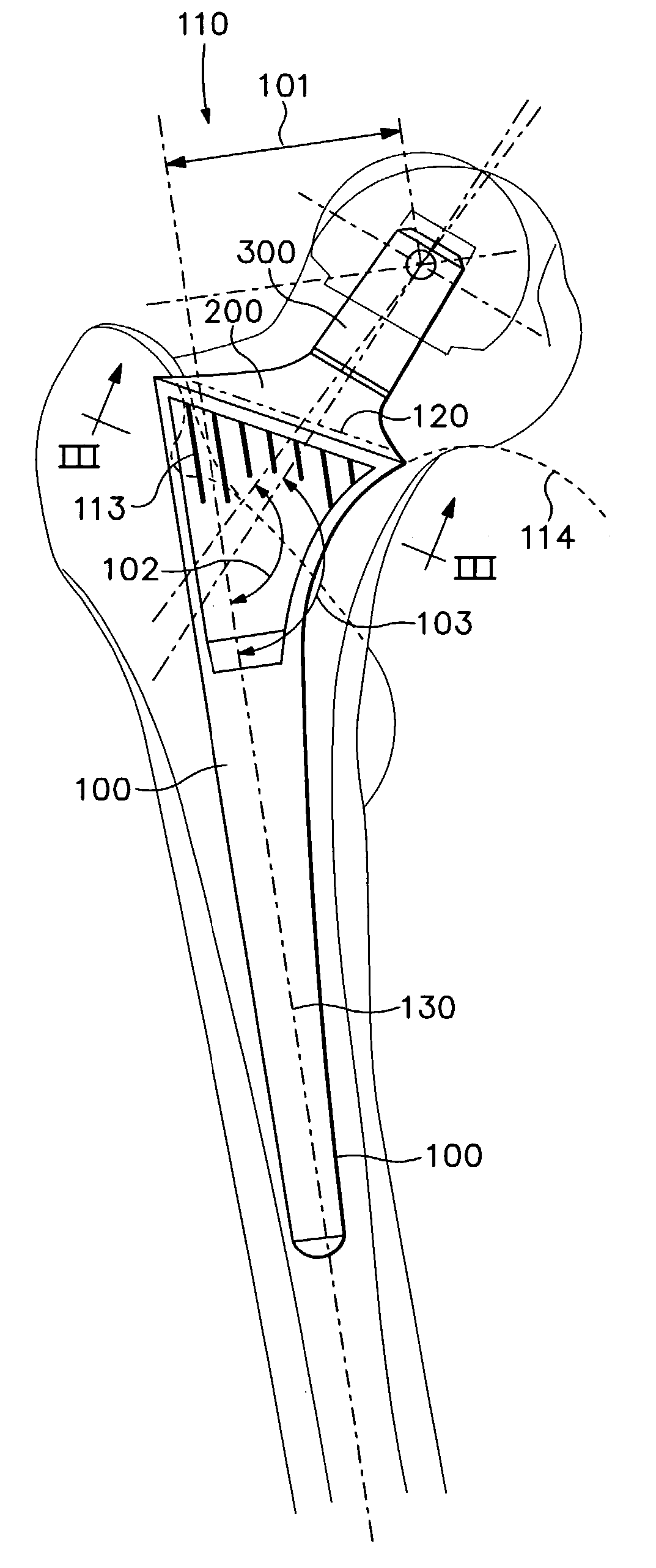
[0006] One of the substantive elements of the prosthesis stem is the straight-line opening of the medullary canal through the greater trochanter (FIG. 01 / 110). The entire neck of the femur (FIG. 01 / 120) is preserved through the osteotomy. The design of the stem (FIG. 01 / 100) allows it to be inserted in a straight line, provided that a guide instrument in the opening canal can be inserted into the medullary canal without encountering resistance. This is the case when the opening has been executed correctly along the dorsal wall of the neck in a straight extension of the canal axis through the greater trochanter. The dorsal wall of the neck forms a straight line with the dorsal wall of the medullary canal.

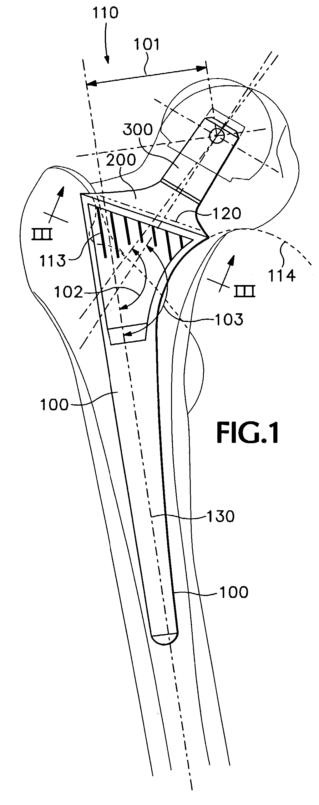
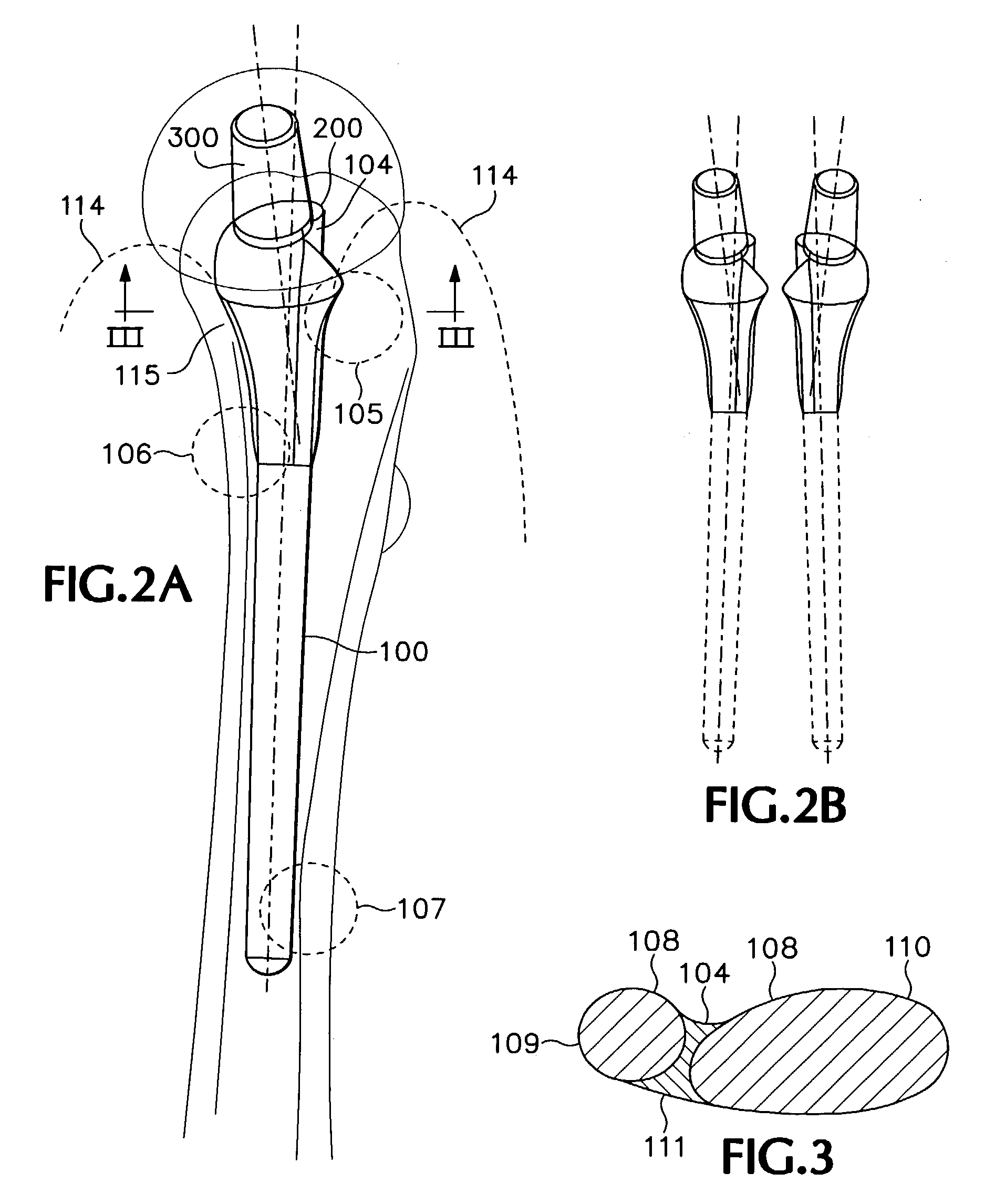
[0007] The design of the prosthesis takes this anatomy into account and utilizes a cylinder (FIG. 03 / 109) as a design element located around the canal axis (FIG. 01 / 130) around which the stem is designed to coincide with the anatomical clearances (FIG. 02.1), which results in symmetr...


PUM


Abstract

The present invention essentially relates to a hip joint endoprosthesis stem for cement-free or cemented anchoring in bones that is anchored in the femural neck and in the proximal metaphysis and preserves the internal spongiosa and compact structures that reinforce the femur, that gives the design element axial access to the medullary canal, and possesses parabolically curved outer surfaces to optimize the transfer of force to the bone.

Description

[0001] Anatomically, there is little correlation between the morphology of the diaphysis and the structure of and loads on the metaphysis. However, the physiological laws of force transfer that dictate that the bone will be most strongly reinforced at the locations where the strongest loads are encountered do apply. The loading of the bone is reflected in its structure. These principles can be used in designing a prosthesis, in particular in taking the prosthesis interface into account. It has been found that the best long-term results are not obtained with a prosthesis that most closely duplicates the compact exterior geometry of the bone (custom-made prostheses), but rather with one that possesses the reinforcing structures of the bone in an optimal manner (Draenert, K., et al., 1999, Manual of Cementing Technique, Berlin, Heidelberg: Springer). The object of this invention is to provide the reinforcing structures in the proximal femur, to apply the load to the bone proximally, an...

Claims


Application Information

Patent Timeline
Patent Type & Authority Applications(United States)
IPC IPC(8): A61F2/00A61F2/30A61F2/36A61F2/46
CPCA61F2/36A61F2310/00131A61F2/367A61F2/4607A61F2/4684A61F2002/30133A61F2002/30332A61F2002/30708A61F2002/30795A61F2002/30797A61F2002/3082A61F2002/30828A61F2002/30879A61F2002/30892A61F2002/3625A61F2002/365A61F2002/4631A61F2220/0033A61F2230/0015A61F2250/0084A61F2310/00017A61F2310/00023A61F2310/00029A61F2/3662
Inventor DRAENERT, KLAUSBLAESIUS, KLAUS
Owner THURGAUER KANTONALBANK A CHARTERED IN & EXISTING UNDER THE LAWS OF SWITZERLAND THAT MAINTAINS ITS PRINCIPAL OFFICES AT
Why Eureka
Try Eureka