Flow meter having airflow sensor

a flow meter and sensor technology, applied in the field of flow meter, can solve the problems of easy damage to the membrane, difficult to eliminate with the air filter, and damage to the sensing part of the flow meter

Inactive Publication Date: 2003-09-18
DENSO CORP
View PDF0 Cites 14 Cited by
  • Summary
  • Abstract
  • Description
  • Claims
  • Application Information

AI Technical Summary

Benefits of technology

[0013] Since the flat surface of the contraction part is formed at least upstream of the sensing part, the air to measure flows along the flat surface of the contraction part and in parallel with the surface of the sensing part when the airflow enters the passage and flows near the sensing part. Meanwhile, the airflow is favorably straightened. Accordingly, the collision of the particles in acute angles against the sensing part is inhibited. Therefore, impulsive force generated when the particles collide with the sensing part is reduced, and the damage in the sensing part or adhesion of contaminants to the sensing part is inhibited. In addition, the airflow is favorably narrowed near the contraction part. Accordingly, the speed of the airflow is increased and the airflow is stabilized. As a result, the flow rate of the air is measured accurately.

Problems solved by technology

However, the intake air also includes particles that have relatively small diameters (hundreds of micrometers, for instance) and are difficult to eliminate with the air filter.
In a case where the particles having relatively small diameters enter the passage, a sensing part of the flow meter might be damaged if the particles collide with the sensing part, for instance, at a speed of tens of meters per second.
Therefore, the membrane will be easily damaged if the particles collide with it.
However, the particles have some weight and inertia.
Therefore, there is a possibility that the flow of the particles might not be straightened sufficiently compared with the airflow, depending on the shape of the contraction part.
Accordingly, the particles whose flow is not straightened sufficiently might collide with the sensing part and might damage the sensing part.
However, the effect of the folded parts is not enough to fully prevent the particles from colliding with the sensing part.
As a result, the sensing part might be damaged by the particles, or the detection accuracy might be degraded because of adhesion of contaminants to the sensing part.

Method used


Image

  • Flow meter having airflow sensor
  • Flow meter having airflow sensor
  • Flow meter having airflow sensor

Examples


first embodiment

[0024] (First Embodiment)

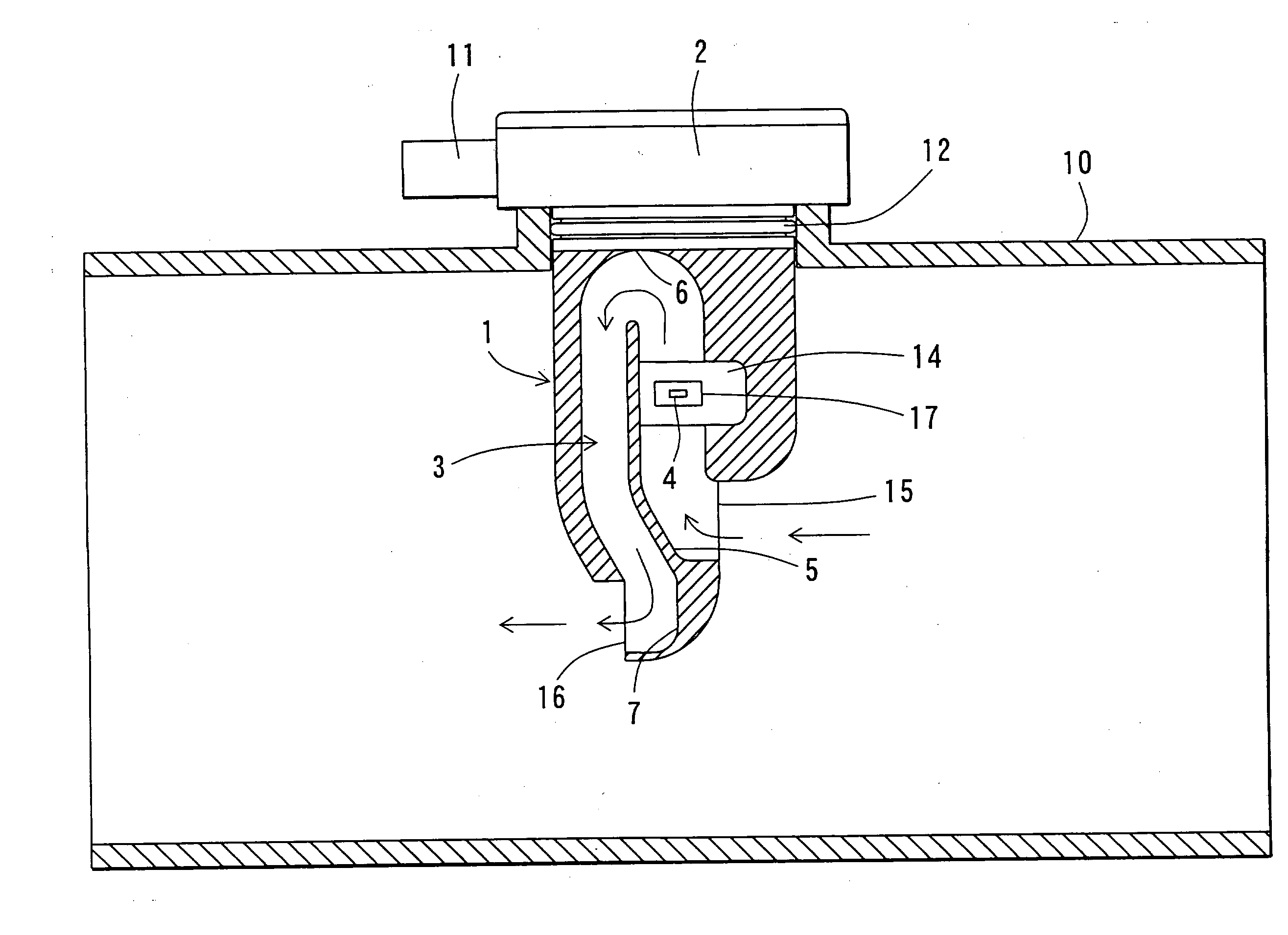
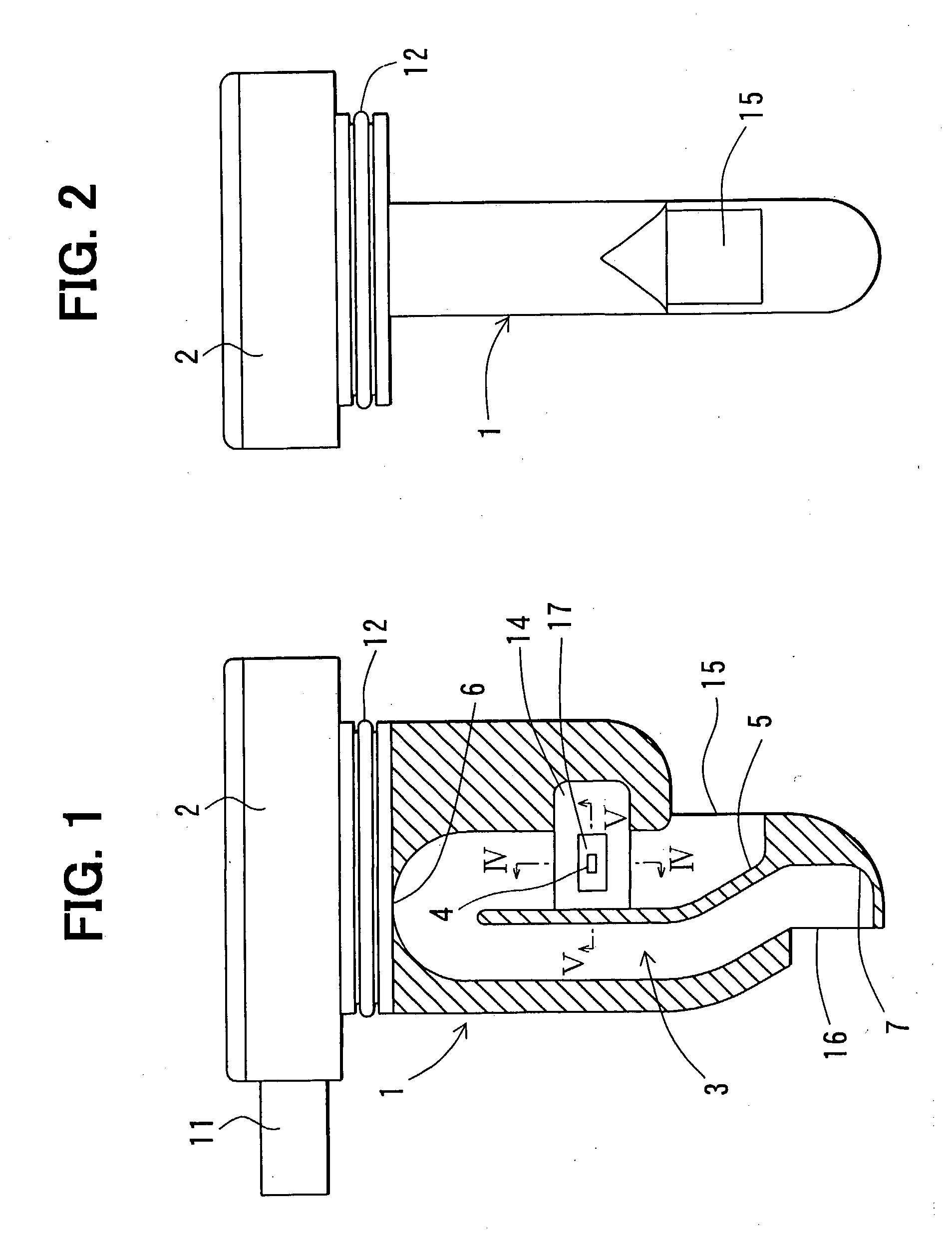
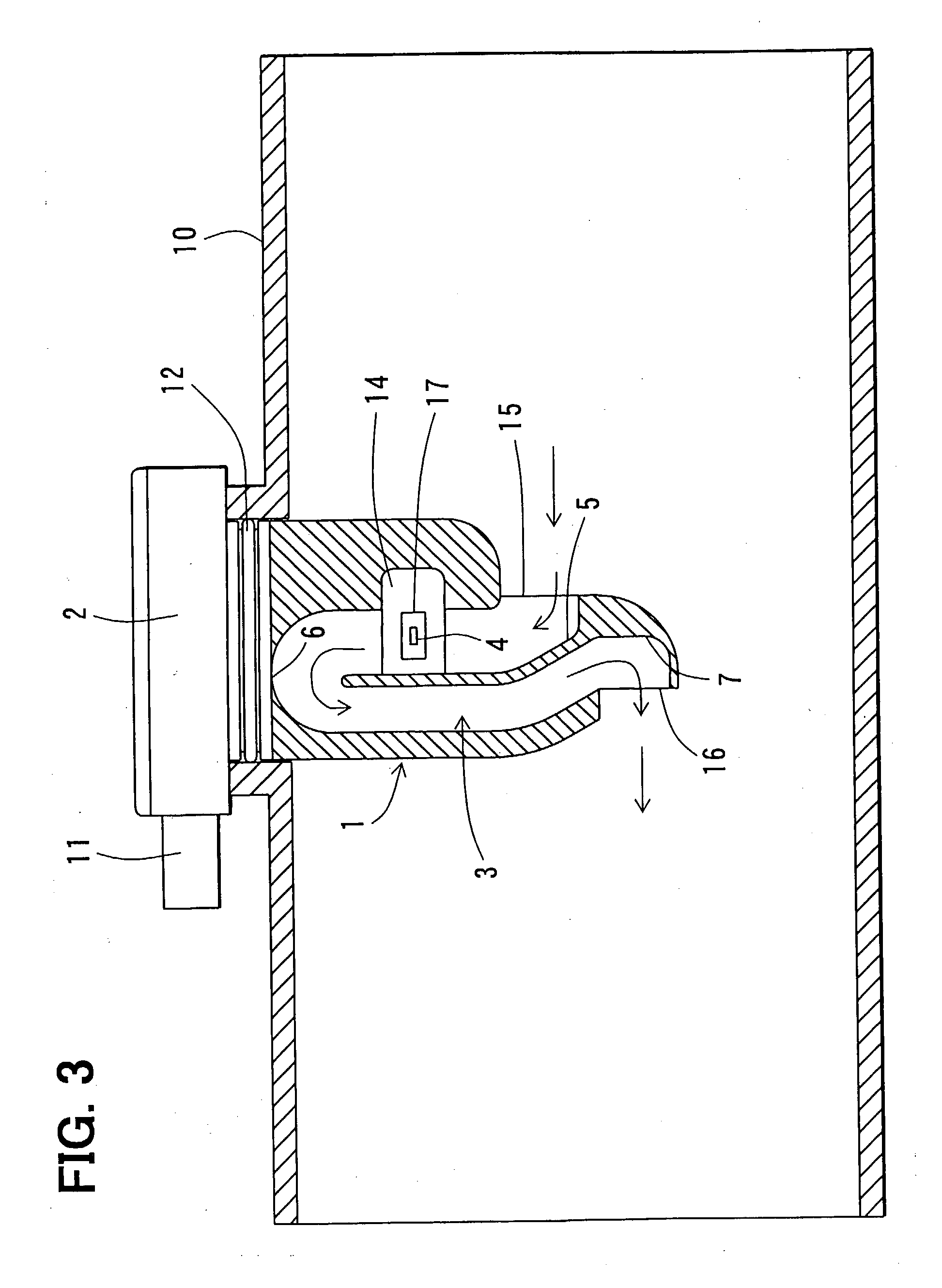
[0025] Referring first to FIG. 1, a flow meter is illustrated. A passage 3 for introducing and carrying air to measure is formed in a main body 1 of the flow meter. The flow meter has a sensing part 4 on a base 14 formed in the passage 3. The sensing part 4 is exposed to the airflow, and measures the flow rate of the air. The passage 3 is a bypass passage for branching and carrying part of the air flowing through an intake pipe 10 of an internal combustion engine and the like. As shown in FIG. 1, the passage 3 is formed generally in the shape of a reversed letter `U` (or in a sigmoid shape). The cross-section of the passage 3 is formed in a rectangular shape as shown in FIG. 5. An upstream end of the passage 3 in the right side in FIG. 1 provides an inlet 15 and a downstream end thereof in the left side in FIG. 1 provides an outlet 16.

[0026] An inlet side bent part 5 is formed in the passage 3 near the inlet 15. On the other hand, an outlet side bent part 7 ...

second embodiment

[0039] (Second Embodiment)

[0040] The second embodiment of the present invention is illustrated in FIG. 7. As shown in FIG. 7, a contraction part 30 is formed on the inner surface of the passage 3 near the sensing part 4. The contraction part 30 has a flat surface 30a parallel to the surface of the sensing part 4. The flat surface 30a extends longer than the sensing part 4, upstream and downstream of the airflow. Another contraction part 31 is formed on the inner surface of the passage 3 opposite from the sensing part 4. The contraction parts 30, 31 are formed symmetrically with each other.

[0041] Since the flat surface 30a extends longer than the sensing part 4 upstream and downstream of the airflow, the airflow is favorably narrowed even if a backflow of the air is generated in the passage 3. As a result, the collision of the particles against the surface of the sensing part 4 in acute angles is greatly inhibited, and the damage to the sensing part 4 is reduced.

third embodiment

[0042] (Third Embodiment)

[0043] The third embodiment of the present invention is illustrated in FIG. 8. As shown in FIG. 8, a contraction part 41 formed opposite from the sensing part 4 is smaller than a contraction part 40 formed in the sensing part 4 side. The airflow and the flow of the particles are suitably straightened near the sensing part 4 even in the case in which the contraction part 41 is formed relatively small as shown in FIG. 8.


PUM


Abstract

A flow meter is formed with a passage for introducing and carrying air to measure and has a sensing part disposed in the passage for measuring a flow rate of the air. A contraction part is formed on an inner surface of the passage so that the contraction part faces the sensing part. The contraction part narrows the flow of the air flowing near the sensing part. A flat surface of the contraction part is formed in parallel with the surface of the sensing part and at least upstream of the sensing part. Thus, collision of particles against the sensing part and adhesion of contaminants to the sensing pert are inhibited. Meanwhile, the flow rate of the air is measured stably and accurately.

Description

[0001] This application is based on and incorporates herein by reference Japanese Patent Application No. 2002-70567 filed on Mar. 14, 2002.[0002] 1. Field of the Invention[0003] The present invention relates to a flow meter for measuring flow rate of air and in particular to a flow meter applied to an intake air flow meter for an internal combustion engine.[0004] 2. Description of Related Art[0005] Conventionally, a flow meter having a membrane airflow sensor is used for measuring a flow rate of intake air of an internal combustion engine. The airflow sensor is disposed in a passage carrying the air to measure.[0006] An air filter is disposed in an intake system of the engine in order to eliminate particles such as sand, which are included in the intake air and have relatively large diameters. However, the intake air also includes particles that have relatively small diameters (hundreds of micrometers, for instance) and are difficult to eliminate with the air filter. In a case where...

Claims


Application Information

Patent Timeline
Patent Type & Authority Applications(United States)
IPC IPC(8): G01F1/00F02D35/00G01F1/684G01F15/12
CPCG01F1/6842
Inventor KOHNO, YASUSHIYAMAMOTO, TOSHIMASAWADO, HIROYUKIYOSHIOKA, TETSUO
Owner DENSO CORP
Why Eureka
Try Eureka