Method and apparatus for reducing DC offsets in communication systems using universal frequency translation technology
Inactive Publication Date: 2003-09-25
PARKER VISION INC
View PDF99 Cites 14 Cited by
Summary
Abstract
Description
Claims
Application Information
AI Technical Summary
This helps you quickly interpret patents by identifying the three key elements:
Problems solved by technology
Method used
Benefits of technology
Problems solved by technology
However, because conventional signal processing technology is limited in operational speed, conventional signal processing technology cannot easily demodulate a baseband signal from higher frequency modulated carrier signal directly.
As a
Method used
Image
Click on the blue label to locate the original text in one second.
Reading with bidirectional positioning of images and text.
Examples
Embodiment Construction
[0191] 7.0 DC Offset, Re-radiation, and Dynamic Range Considerations and Corrections
[0192] 7.1 Overview of DC Offset and Re-radiation
[0193] 7.1.1 Introduction
[0194] 7.1.2 A Basic DC Offset Model
[0195] 7.1.3 Clock Modulation via PN Code
[0196] 7.1.3.1 Interpretation of Rxx(T) and Required Leakage
[0197] 7.1.3.2 Charge Injected DC Offset
[0198] 7.1.3.3 Clock Waveform Impact on CI Induced Offsets
[0199] 7.1.3.4 Bench Example
[0200] 7.1.3.5 Complementary Architecture
[0201] 7.1.3.6 Spreading Code Results
[0202] 7.1.4 UFD Module DC Offsets from Non-Linearities
[0203] 7.2 Example Embodiments to Address DC Offset and Re-radiation Problems
[0204] 7.2.1 DC Offset
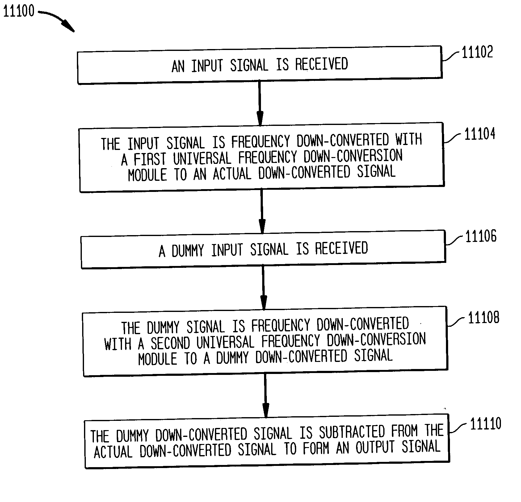
[0205] 7.2.1.1 Reducing DC Offset by Spectral Spreading and De-spreading
PUM
Abstract
Methods, systems, and apparatuses for down-converting an electromagnetic (EM) signal by aliasing the EM signal, and applications thereof are described herein. Reducing or eliminating DC offset voltages and re-radiation generated when down-converting an electromagnetic (EM) signal is also described herein. Down-converting a signal and improving receiver dynamic range is also described herein.
Description
[0001] "Method and System for Frequency Up-Conversion," Ser. No. 09 / 176,154, filed Oct. 21, 1998.[0002] "Method and System for Ensuring Reception of a Communications Signal," Ser. No. 09 / 176,415, filed Oct. 21, 1998.[0003] "Integrated Frequency Translation And Selectivity," Ser. No. 09 / 175,966, filed Oct. 21, 1998.[0004] "Applications of Universal Frequency Translation," Ser. No.09 / 261,129, filed Mar. 3, 1999.[0005] "Method and System for Down-Converting Electromagnetic Signals Having Optimized Switch Structures," Ser. No. 09 / 293,095, filed Apr. 16, 1999.[0006] "Method and System for Down-Converting Electromagnetic Signals Including Resonant Structures for Enhanced Energy Transfer," Ser. No.09 / 293,342, filed Apr. 16, 1999.[0007] "Method and System for Frequency Up-Conversion with a Variety of Transmitter Configurations," Ser. No. 09 / 293,580, filed Apr. 16, 1999.[0008] "Integrated Frequency Translation and Selectivity with a Variety of Filter Embodiments," Ser. No. 09 / 293,283, filed ...
Claims
Application Information
Patent Timeline
Application Date:The date an application was filed.
Publication Date:The date a patent or application was officially published.
First Publication Date:The earliest publication date of a patent with the same application number.
Issue Date:Publication date of the patent grant document.
PCT Entry Date:The Entry date of PCT National Phase.
Estimated Expiry Date:The statutory expiry date of a patent right according to the Patent Law, and it is the longest term of protection that the patent right can achieve without the termination of the patent right due to other reasons(Term extension factor has been taken into account ).
Invalid Date:Actual expiry date is based on effective date or publication date of legal transaction data of invalid patent.