Replaceable electrical device for drilling tool

Inactive Publication Date: 2003-10-02
BAKER HUGHES INC
View PDF0 Cites 27 Cited by
  • Summary
  • Abstract
  • Description
  • Claims
  • Application Information

AI Technical Summary

Problems solved by technology

Disassembly of the tool makes replacing a battery pack time consuming and, in certain cases, is impossible at the job site.

Method used


Image

  • Replaceable electrical device for drilling tool
  • Replaceable electrical device for drilling tool
  • Replaceable electrical device for drilling tool

Examples


Embodiment Construction

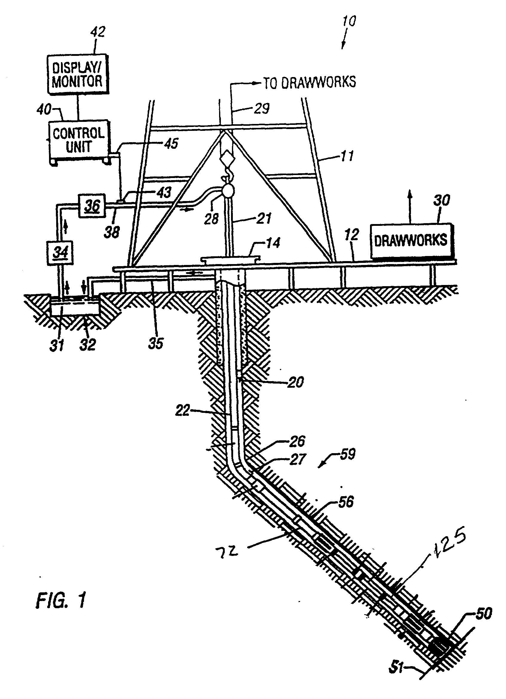
[0016] FIG. 1 shows a schematic diagram of a drilling system 10 having a downhole assembly containing a downhole sensor system and the surface devices according to one embodiment of present invention. As shown, the system 10 includes a conventional derrick 11 erected on a derrick floor 12 which supports a rotary table 14 that is rotated by a prime mover (not shown) at a desired rotational speed. A drill string 20 that includes a drill pipe section 22 extends downward from the rotary table 14 into a wellbore 26. A drill bit 50 attached to the drill string downhole end disintegrates the geological formations when it is rotated. The drill string 20 is coupled to a drawworks 30 via a kelly joint 21, swivel 28 and line 29 through a system of pulleys (not shown). During the drilling operations, the drawworks 30 is operated to control the weight on bit and the rate of penetration of the drill string 20 into the wellbore 26. The operation of the drawworks is well known in the art and is thu...


PUM


Abstract

A downhole tool for use in a wellbore, comprises a tubular member, such as a drill collar housing, in a drill string. The tubular member has at least one cavity formed on an external surface. At least one housing is adapted to be insertable and extractable in the cavity without further tool disassembly. The housing has at least one electrical device such as a battery stack disposed within. In another aspect, sensors are disposed in the housing for measuring downhole parameters of interest including, but not limited to, annulus pressure and annulus temperature. A method of replacing an electrical device in a downhole tool, comprises removing a first housing containing the electrical device from a cavity on an external surface of the downhole tool, and installing a second housing containing a second electrical device in the cavity without disassembling the tool further.

Description

[0001] 1. Field of the Invention[0002] The invention relates generally to a tool for use in an oilfield wellbore, and more specifically to an easily replaceable electrical device for use in such a tool.[0003] 2. Description of the Related Art[0004] Tools requiring electrical power are often used for conducting various operations in a wellbore. This creates a need for portable electrical power, preferably power that can be mounted directly onto a downhole tool. One way of providing electrical power downhole is through the use of a battery pack. Typically, the battery pack is constructed of multiple cells mounted in rigid plastic, epoxy, fiberglass, or aluminum shells and is housed in a sonde or in an annular housing mounted in the bore of a downhole tool. One or more cells are typically contained within the battery pack. The cells can be electrically connected in various series or parallel configurations to provide the necessary voltage and current capacities required for the various...

Claims


Application Information

Patent Timeline
IPC IPC(8): E21B47/01
CPCE21B47/01
Inventor DAS, PRALAY K.MARZOUK, JOE
Owner BAKER HUGHES INC
Why Eureka
Try Eureka