
Full duplexing for power line data communications

a technology of power line data communication and duplex communication, applied in the field of full duplex communication, can solve the problems of affecting the hybrid isolation between transmitter and receiver, affecting the output stage of high frequency power amplifiers, and falling within the frequency band of receivers,

Inactive Publication Date: 2003-10-30
AMBIENT CORPORATION
View PDF8 Cites 39 Cited by
  • Summary
  • Abstract
  • Description
  • Claims
  • Application Information

AI Technical Summary

Problems solved by technology

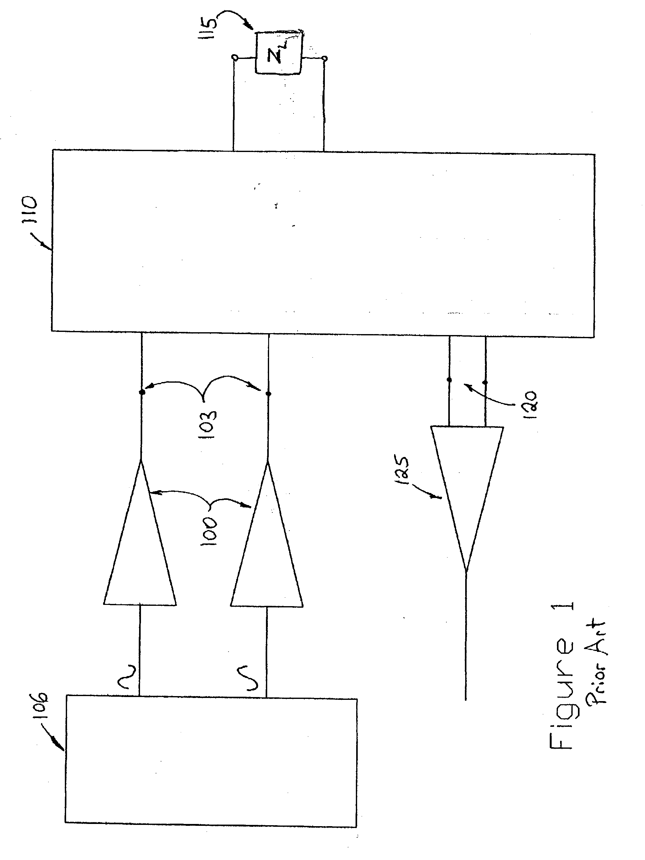
Unfortunately, high frequency power amplifiers like those typically used in the output stage of the transmitter are not perfectly linear.
Some of these IM products will fall within the receiver's frequency band and interfere with incoming signals from distant second modems.
In the case of analog telephone networks such accurate impedance matching is not a problem, but for power line networks the load impedance seen at the powerline terminals varies widely over the frequency bands of interest, and the hybrid's isolation between transmitter and receiver may be severely degraded.
The signal-to-noise ratio at the receiver may be degraded significantly when a substantial amount of spurious transmitter output falls within the receiver's input frequency band and power line impedance mismatch causes some of that spurious energy to reach the receiver's input terminals.
That can cause data errors or force a reduction of the data rate to maintain acceptable error rates.

Method used


Image

  • Full duplexing for power line data communications
  • Full duplexing for power line data communications
  • Full duplexing for power line data communications

Examples


Embodiment Construction

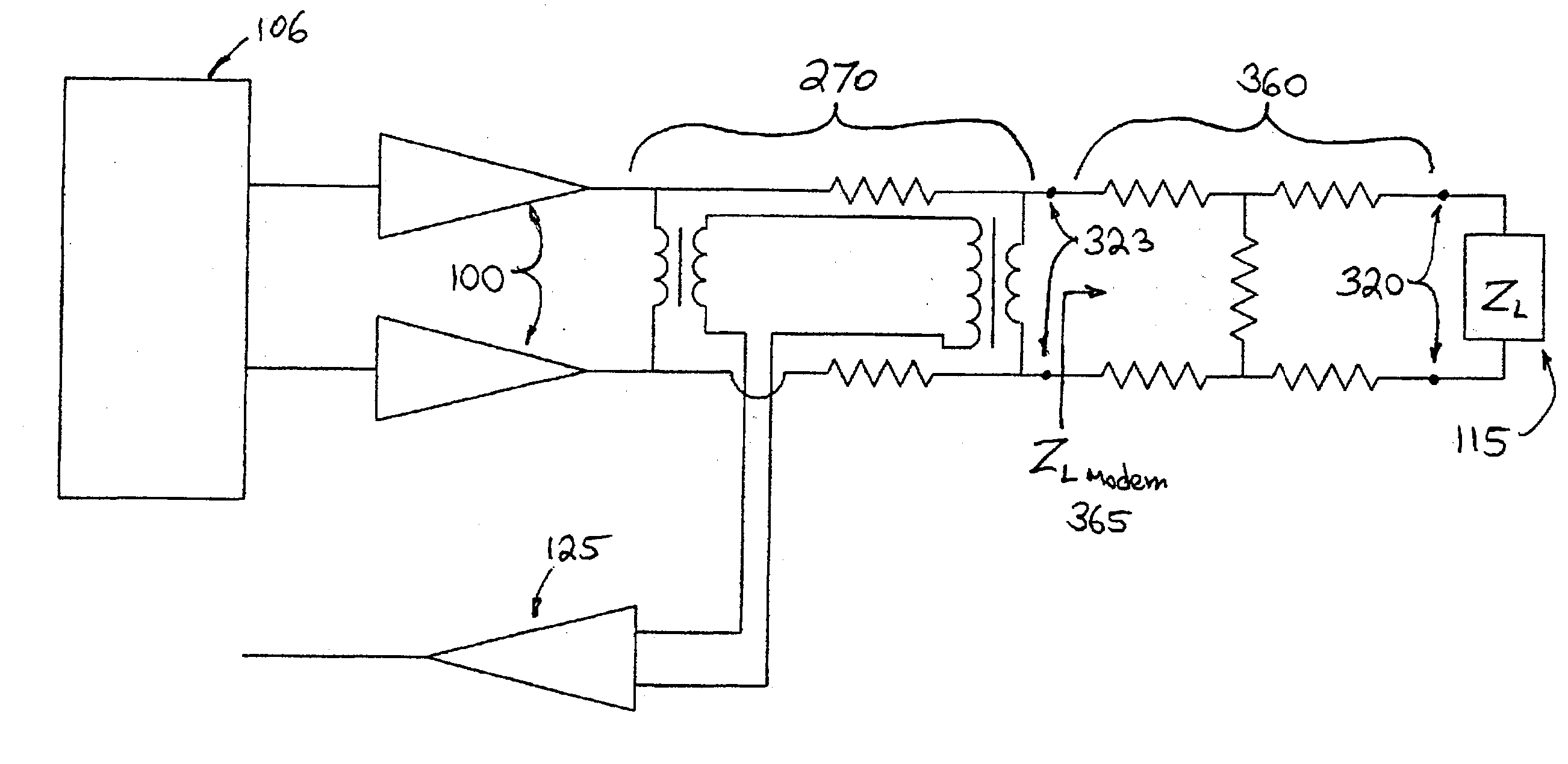
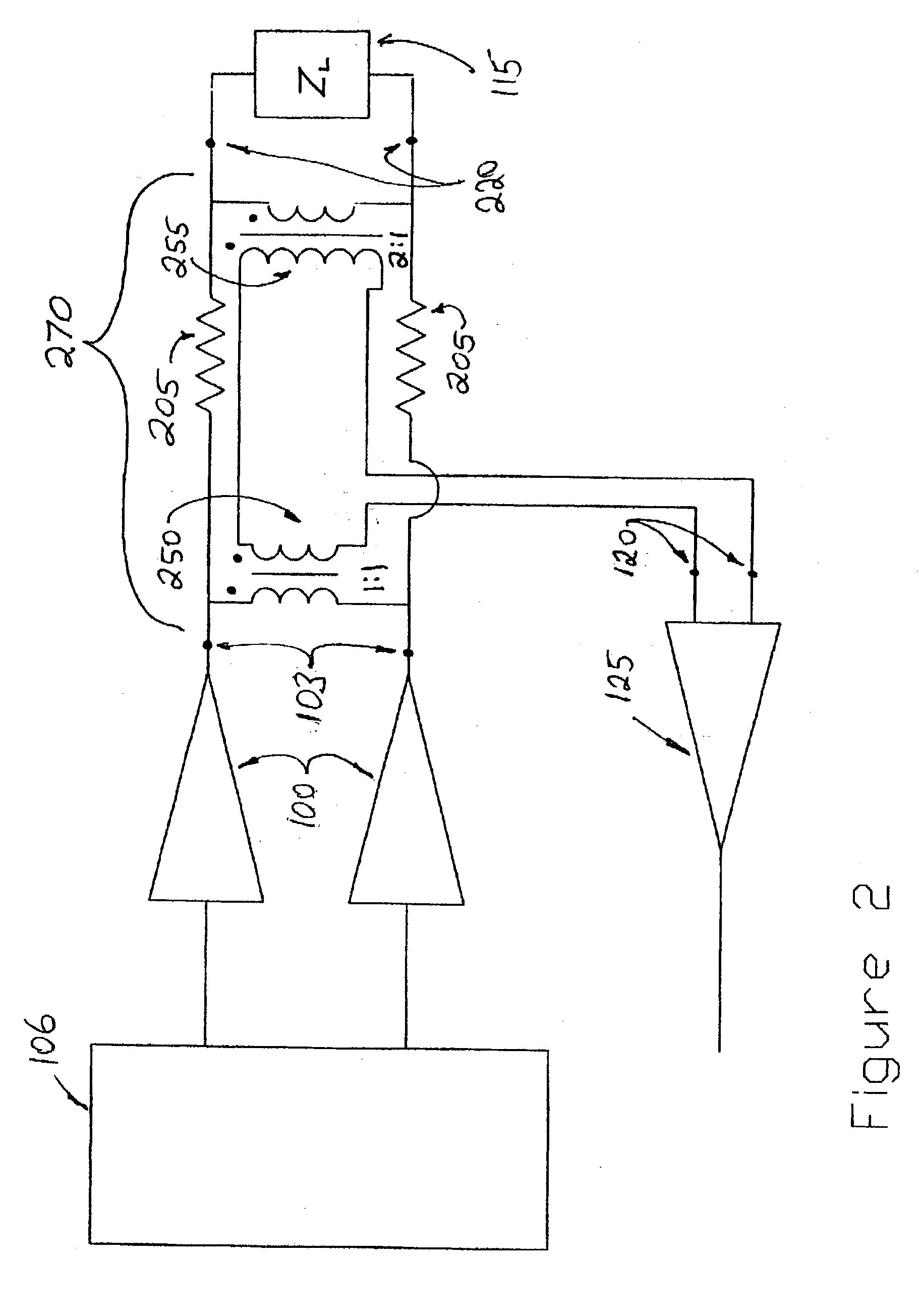
[0017] FIG. 2 shows a hybrid coupler 270 for full duplexing according to one embodiment of the present invention. Typical solid state high frequency line drivers 100, such as may be used as modem transmitter output stages, often have near-zero output impedance. Impedance matching and current limiting is achieved through external resistors 205. A particular powerline nominal impedance, e.g. 50 ohms, is used for purposes of illustrating a design. For power line loads, represented here by Z.sub.L 115 that display the nominal 50 ohms, the transmitter voltage between terminal pair 220 will be one half that at driver terminal pair 103.

[0018] If the voltage across terminals 220 could be doubled and subtracted from the voltage across terminals 103, the resulting voltage would perfectly cancel the transmitter voltage. FIG. 2 shows this accomplished by the addition of transformers 250 and 255, with the turns ratio of transformer 255 being double that of transformer 250, and where secondaries ...


PUM


Abstract

There is provided a coupling circuit for a full duplex modem having a transmitter and a receiver. The coupling circuit includes (a) a first transformer having a primary winding and a secondary winding, where the primary winding is coupled to the transmitter, (b) a second transformer having a primary winding and a secondary winding, where the primary winding of the second transformer is coupled to a communications line, and (c) a resistance between a terminal of the primary winding of the first transformer and a terminal of the primary winding of the second transformer. The secondary windings of the first and second transformers are connected in series, with opposing phase, and coupled to the receiver to minimize a level of a signal from the transmitter from reaching the receiver.

Description

[0001] The present application is claiming priority of U.S. Provisional Patent Application Serial No. 60 / 376,109, filed on Apr. 29, 2002.[0002] 1. Field of the Invention[0003] The present invention generally relates to coupling communication signals to electrical power distribution systems, and more specifically to full duplex communications over electric power lines and other electrical lines having widely varying drive point impedance.[0004] 2. Description of the Related Art[0005] Data communications can be accomplished between modems connected via electric power lines, but widely varying drive point impedance of such power lines should be considered. Typically, a power line modem may include a high frequency transmitter and a high frequency receiver that need to operate simultaneously over different frequency bands. In the case of spread spectrum modems, the transmitting and receiving frequency bands are relatively broad. Unfortunately, high frequency power amplifiers like those ...

Claims


Application Information

Patent Timeline
Patent Type & Authority Applications(United States)
IPC IPC(8): H04B3/03H04B1/74H04B3/56
CPCH04B3/03H04B2203/5483H04B2203/5425H04B3/56H04B3/54H04B1/38G05F1/12
Inventor CERN, YEHUDA
Owner AMBIENT CORPORATION
Learn More