
Point of sale (POS) based bar code reading systems having light-pipe based bar code read indication subsystems integrated therein

a bar code and reading system technology, applied in the field of retail point of sale (pos) scanning and checkout systems, can solve the problems of increasing visual tracking difficulty, increasing the difficulty of visual price verification, and increasing the difficulty of visual tracking for customers to visually track scanned items

Inactive Publication Date: 2003-11-06
METROLOGIC INSTR
View PDF8 Cites 31 Cited by
  • Summary
  • Abstract
  • Description
  • Claims
  • Application Information

AI Technical Summary

Benefits of technology

[0011] Accordingly, a primary object of the present invention is to provide a novel POS-based bar code symbol reading system having an integrated customer-kiosk terminal, and being essentially free of the shortcomings and drawbacks of prior art POS-based systems and methodologies.
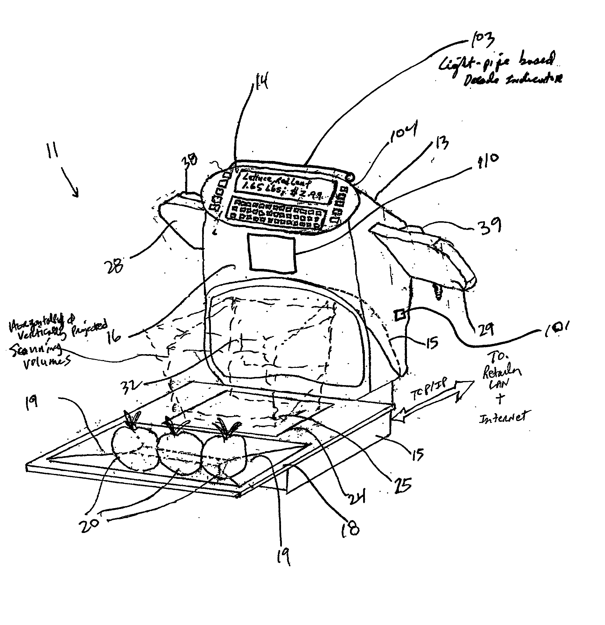
[0013] Another object of the present invention is to provide a novel POS-based bar code reading system with an integrated Internet-enabled customer-kiosk terminal, wherein a POS-based bioptical laser scanning bar code reading unit is integrated with a cashier-scale-terminal / customer-ki-osk-terminal module via a housing interconnection technique, and wherein the POS-based bioptical scanning unit supports a produce weigh tray having a recessed surface region for slidably receiving the full weight of produce items under gravitational loading so that the full weight of the produce items to be purchased is accurately measured by an electronic produce scale integrated within the bottom portion of the POS-based bioptical scanning unit.
[0017] Another object of the present invention is to provide such a POS-based bar code reading system with an integrated Internet-enabled customer-kiosk terminal, wherein a LED-driven light-pipe based bar code read indication subsystem is mounted through the system housing so that both the cashier and customer alike can be visually cued (i.e. alarmed) each time a scanned bar code symbol has been successfully scanned and decoded (i.e. read), in an aesthetically pleasing, if not beautiful manner, to the enjoyment of the cashier and customer at the POS station.
[0027] Another object of the present invention is to provide such a POS-based bar code reading cash register system with an integrated Internet-enabled customer-kiosk terminal, wherein a LED-driven light-pipe based bar code read indication subsystem is mounted through the system housing so that both the cashier and customer alike can be visually cued (i.e. alarmed) each time a scanned bar code symbol has been successfully scanned and decoded (i.e. read), in an aesthetically pleasing, if not beautiful manner, to the enjoyment of the cashier and customer at the POS station.
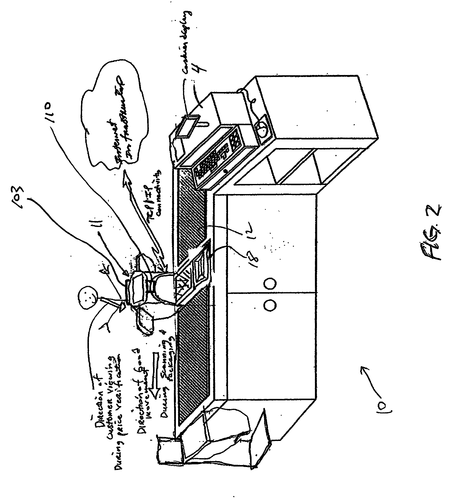
[0029] Another object of the present invention is to provide a novel POS-based bar code reading cash register system with an integrated and Internet-enabled customer-kiosk terminal, wherein by virtue of its novel construction, the POS-based bar code reading cash register system with an integrated Internet-enabled customer-kiosk Terminal is capable of performing all of the functions enabled by prior art POS-based checkout counter systems, with the advantage that the system of the present invention does so in a system form factor having a unitary construction that occupies only a fraction of the space required by the prior art, while enabling a variety of Internet-based services that offer real value to customers as they are checking out their purchase items.
[0040] FIG. 3A is a perspective view of the first illustrative of the POS-based bar code reading system with an integrated Internet-enabled customer-kiosk terminal, showing a POS-based bioptical laser scanning bar code reading unit integrated with a cashier-scale-terminal / customer-kiosk--terminal module via a housing interconnection technique, wherein the POS-based bioptical scanning unit supports a produce weigh tray having a recessed surface region for slidably receiving the full weight of produce items under gravitational loading so that the full weight of the produce items to be purchased is accurately measured by an electronic produce scale integrated within the bottom portion of the POS-based bioptical scanning unit;

Problems solved by technology

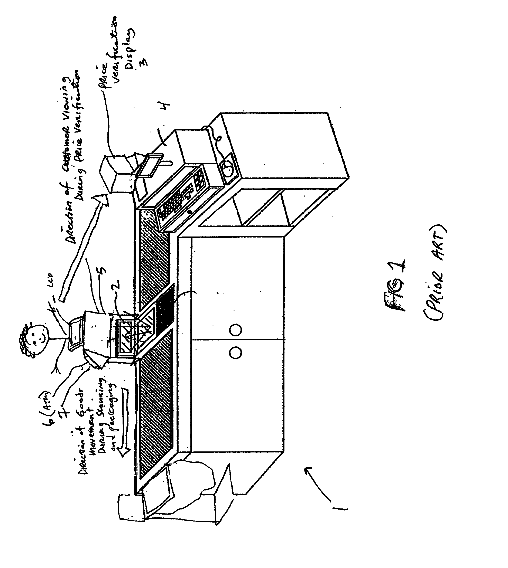
Conventional checkout counter arrangements of such design render it difficult for customers to visually track scanned items with their purchased price information being displayed on the price verification display monitor 3.
Visual tracking becomes even more difficult when large checkout lines are formed and the cashier is pressured to scan purchase items at the highest speeds humanly possible.
When the customer is accompanied by children, visual price verification tends to become even more difficult.
Typically, this scanner / ATM arrangement occupies a large amount of valuable space at the retail checkout counter, and generally detracts from the overall appearance of the checkout counter where products and produce are purchased and sold.
Moreover, while most price verification display monitors 3 located above the cash register terminal are capable of displaying advertisements and promotions to the customers as they checkout their product purchases, such monitors are not capable of performing any other functions in conventional POS-based checkout environments.
Also, the LED indicator lights and audible transducers used in conventional POS based scanners, to indicate that a scanned bar code symbol has been successful scanned and decoded (i.e. read), generally detract from the aesthetic qualities of conventional POS based systems and overall end-user experience enabled at POS-based checkout environments.

Method used


Image

  • Point of sale (POS) based bar code reading systems having light-pipe based bar code read indication subsystems integrated therein
  • Point of sale (POS) based bar code reading systems having light-pipe based bar code read indication subsystems integrated therein
  • Point of sale (POS) based bar code reading systems having light-pipe based bar code read indication subsystems integrated therein

Examples


Embodiment Construction

[0075] Referring now to the figure drawings, the Objects of the Present Invention will be best understood by reading the following Detailed Description Of The Illustrative Embodiments in conjunction with the appended Drawings, wherein like structures and elements are indicated by like reference numerals.

[0076] First Illustrative Embodiment of the POS-Based Laser Scanning Bar Code Reading System With an Integrated Internet-Enabled Customer-Kiosk Terminal of the Present Invention

[0077] In FIG. 2, there is shown a POS-based checkout station 10 configured in accordance with the principles of the present invention. In this checkout station design, a first illustrative embodiment of the POS-based bar code reading system with internet-enabled customer-kiosk terminal 11 is shown. This system is installed in a countertop surface 12 so that (i) the cashier is capable of entering product price information into the system 4 via a cashier-scale terminal 14 during the checking out of weighed purc...


PUM


Abstract

Novel POS-based bar code symbol reading systems are disclosed having an integrated customer-kiosk terminal. Also disclosed are novel POS-Based Bar Code Reading Cash Register Systems having Integrated Internet-Enabled Customer-Kiosk Terminals.

Description

CROSS-REFERENCE TO RELATED U.S. APPLICATIONS[0001] This is a Continuation-in-Part of copending Application Serial No. ______ [Attorney Docket No. 108-173USA000, not yet assigned] entitled "Modular Omnidirectional Bar Code Symbol Scanning System With At Least One Service Port For Removable Installation Of A Scan Module Insert" by Mark Lucera, et al. filed May 3, 2002;. Ser. No. 10 / 053,486 filed Jan. 16, 2002; Ser. No. 10 / 045,577 filed Jan. 11, 2002; application Ser. No. 10 / 045,605 filed Jan. 11, 2002; Ser. No. 09 / 990,585 filed Nov. 21, 2001; Ser. No. 09 / 999,687 filed Oct. 31, 2001; Ser. No. 09 / 954,477 filed Sep. 17, 2001; and Ser. No. 09 / 551,887 filed Apr. 18, 2000; and is also related to International Application PCT / US01 / 44011 filed Nov. 21, 2001; each of said Applications being owned by Assignee, Metrologic Instruments, Inc., of Blackwood, N.J., and incorporated herein by reference as if fully set forth herein.BACKGROUND OF INVENTION[0002] 1. Field of Invention[0003] The present i...

Claims


Application Information

Patent Timeline
IPC IPC(8): G07G1/00G07G1/12
CPCG06K7/1096G07G1/12G07G1/0018G06K7/1098
Inventor BYUN, SUNGSCHMIDT, MARKJACKSON, RONALDRUSSELL, GARRETTGOOD, TIMOTHY
Owner METROLOGIC INSTR
Learn More