Rotary tool and cutting part comprised in the tool

Inactive Publication Date: 2003-11-13
SANDVIK AB
View PDF10 Cites 62 Cited by
  • Summary
  • Abstract
  • Description
  • Claims
  • Application Information

AI Technical Summary

Problems solved by technology

The problem is that the tolerances do not permit that this be carried out exactly simultaneously, which means that abutment will occur either between the shoulder and the stop face or between the conical part and the conical seating.

Method used


Image

  • Rotary tool and cutting part comprised in the tool
  • Rotary tool and cutting part comprised in the tool
  • Rotary tool and cutting part comprised in the tool

Examples


Embodiment Construction

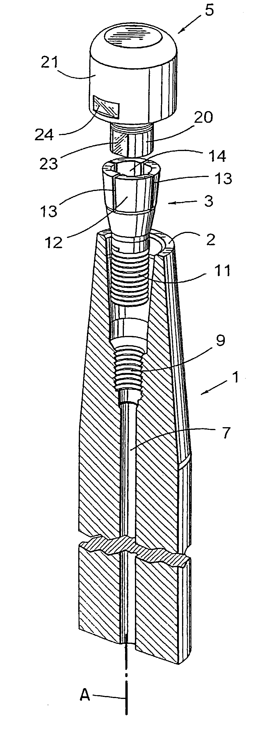
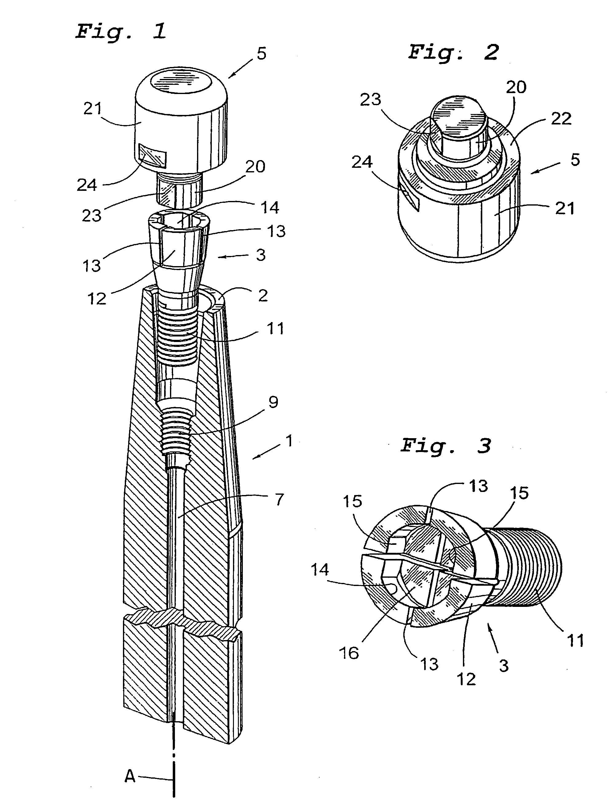
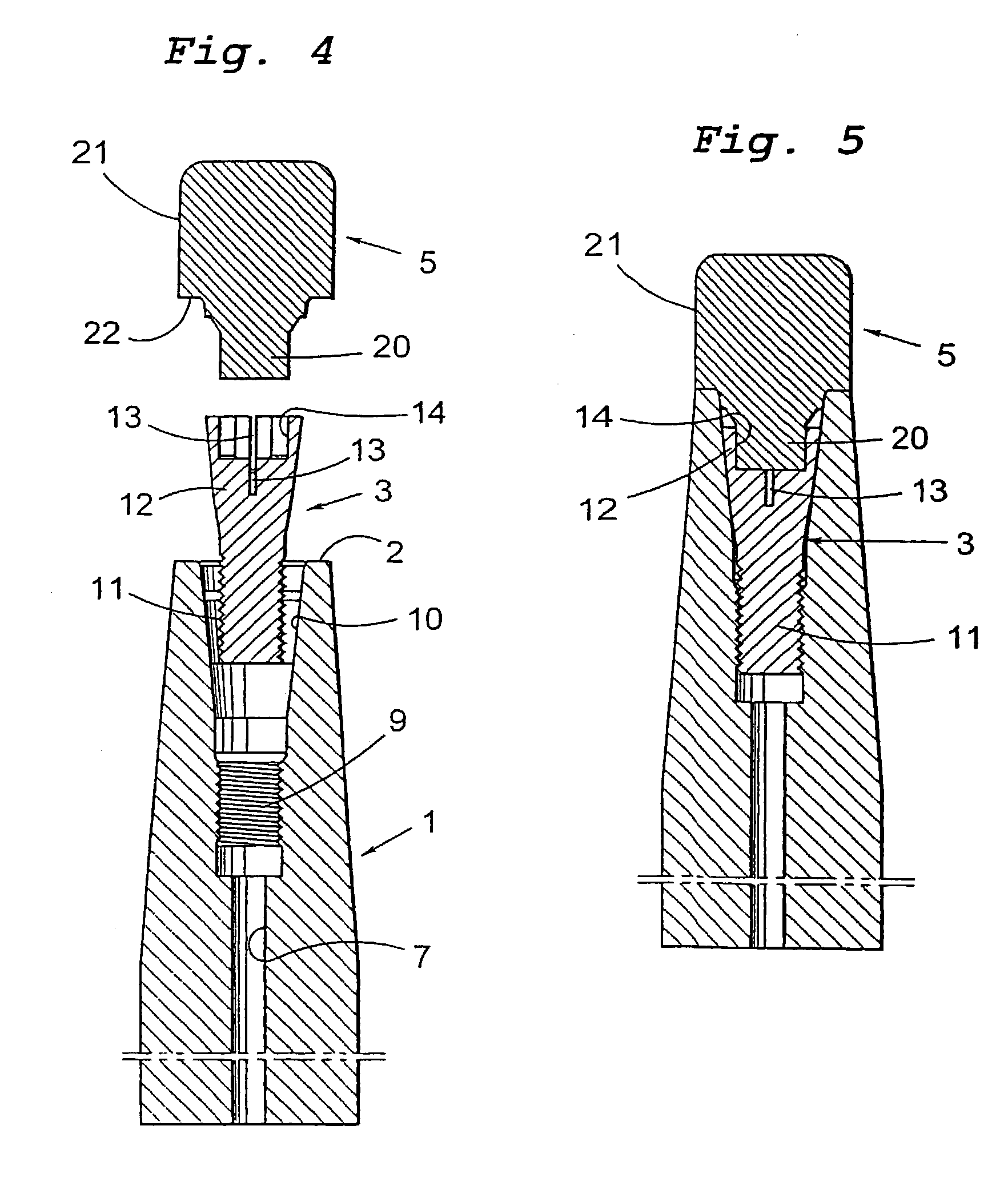
[0020] The rotary tool for chip removing machining according to the present invention shown in FIGS. 1, 4 and 5 comprises a shaft 1, a holder 3 as well as a cutting part 5. The shaft 1 has an end face 2 at a free end thereof. The upper portion of the cutting part 5 is only shown schematically in these figures, i.e. cutting edges, chip channels and the like are not illustrated. A cutting part 5 is shown in FIG. 5A having integral cutting edges E and chip passages P. Alternatively, the cutting part could have cutting edges formed by replaceable cutting inserts (not shown).

[0021] The shaft 1 defines a longitudinal axis A and is provided with a through hole 7 extending axially. As is most clearly seen in FIG. 4, at the free end that will receive the holder 3 and the cutting part 5, the shaft 1 is provided with an internal thread 9 as well as an axially outwardly open, cone-shaped seating 10 situated outside of this thread 9 and at a free end of the shaft. The seating is formed by a surf...


PUM

PropertyMeasurementUnit
cone angleaaaaaaaaaa

Abstract

A rotary tool for chip removing machining, for example a milling cutter or a drill, includes a shaft, a holder, and a cutting part. The shaft has a conical seating arranged in its front end. The holder has a slightly conical recess, whose cross-sectional dimension decreases toward the open end of the recess. The cutting part has a slightly conical pin designed to be received in the recess and has a cross-sectional dimension which increases in the direction of the free end of the pin. The recess is formed by a wall which is elastically flexible in a radial direction. When the holder is drawn axially into the seating, the wall is flexed radially inwardly, causing the conical surface of the recess to tightly grip the conical surface of the pin and create an interference fit of the pin in the recess.

Description

[0001] This application claims priority under 35 U.S.C. .sctn.119 to Patent Application Serial No. 0200852-2 filed in Sweden on Mar. 21, 2002, the entire content of which is hereby incorporated by reference.[0002] The present invention relates to a rotary tool, especially for chip removing machining, the tool, for instance, being a milling cutter or a drill and comprising a shaft, and a conical seating arranged in the shaft. The seating is situated in connection to one end of the shaft. A holder has an externally generally conical portion and members for receipt of a cutting part, as well as members which apply a force on the holder in the axial direction of the shaft. Separately, the invention also relates to a cutting part that constitutes a replaceable part of the tool according to the present invention.PRIOR ART[0003] A modular milling system is previously known from the company SILMAX, which system is marketed under the trademark SHUTTLE SYSTEM. The system comprises a spindle, ...

Claims


Application Information

Patent Timeline
Patent Type & Authority Applications(United States)
IPC IPC(8): B23B31/00B23Q3/12B23B31/11B23B31/20B23B51/00B23C5/10B23C5/20
CPCB23B31/008B23B31/1107B23B31/1122Y10T408/9098B23B2222/28B23B2260/034B23B2265/32B23B31/201B23B31/2073A47C7/546A47C7/624
Inventor KAKAI, ISAKWALLSTROM, LARS-GUNNAR
Owner SANDVIK AB
Why Eureka
Try Eureka