Paint spraying gun

a spray gun and paint technology, applied in the direction of threaded fasteners, liquid spraying apparatuses, fastening means, etc., can solve the problems of no self-locking effect, no self-locking effect can be guaranteed, and significant time-consuming

Inactive Publication Date: 2003-11-20
SATA GMBH & CO KG
View PDF7 Cites 56 Cited by
  • Summary
  • Abstract
  • Description
  • Claims
  • Application Information

AI Technical Summary

Problems solved by technology

This is associated with a significant expenditure of time.
This means that no self-locking effect can be ensured, and that the connection may loosen.
In addition, ...

Method used


Image

  • Paint spraying gun
  • Paint spraying gun
  • Paint spraying gun

Examples


Embodiment Construction

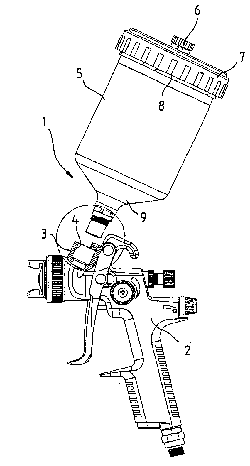
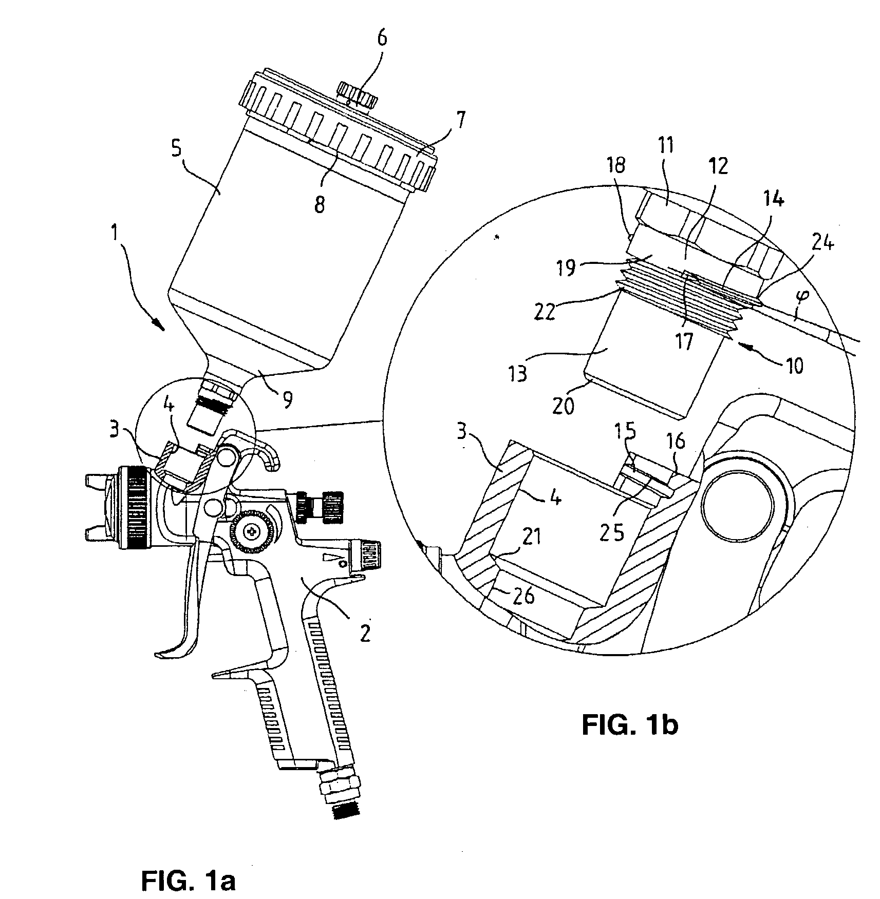
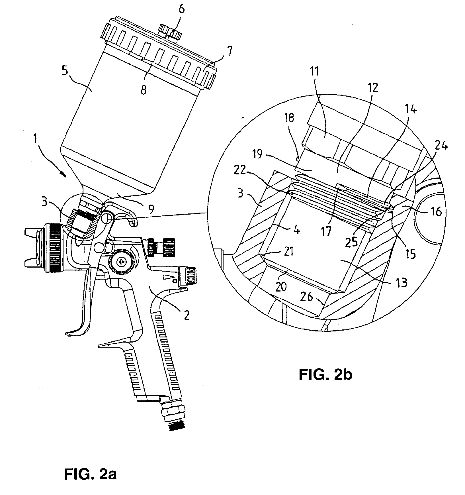
[0027] FIGS. 1a, 1b, 2a and 2b show a paint spraying gun 1, the gun body 2 of which contains a connecting region 3 with a receiving bore 4 for removably attaching a paint receptacle in the form of a gravity feed container 5. A cover 7 that is provided with a drip stop 6 serves to close the gravity feed container 5 of plastic or metal, wherein said cover is removably secured to the top edge of the gravity feed container 5 with the aid of a thread 8 or the like. In its conically tapered bottom section 9, the gravity feed container 5 has a bore with an essentially hollow-cylindrical connecting part 10 firmly inserted therein. The connecting part 10 that, for example, consists of metal, comprises an upper hexagonal installation region 11, a connecting region 12 arranged underneath this, and a bottom guide region 13 that engages into the receiving bore 4.

[0028] A screw-wedge element 14 is arranged on the outer periphery of the cylindrical connecting region 12 such that it extends over pa...


PUM


Abstract

A paint spraying gun with a gun body and a material supply device that can be connected to one another by means of a screw-wedge connection, wherein the screw-wedge connection includes a screw-wedge element that is arranged on the circumference of an essentially hollow-cylindrical connecting part of the material supply device, and a corresponding counter element on the gun body. A new method for connecting the material supply device, which can be inexpensively manufactured and easily handled, and which is characterized by the fact that the screw-wedge element contains a gap and extends over more than half of the circumference of the connecting part, and by the fact that the counter element is arranged on a one-sided projection situated above a receiving bore of the gun body.

Description

[0001] This application is a continuation of International Application No. PCT / EP02 / 13966 filed Dec. 10, 2002, the contents of which are here incorporated by reference in their entirety.[0002] 1. Field of the Invention[0003] The invention pertains to a paint spraying gun, to a connecting part for the material supply device of a paint spraying gun, and to a paint receptacle.[0004] 2. Prior Art[0005] In conventional paint spraying guns, the connection between the gun body and a paint receptacle or another material supply device, e.g., a hose or a pipe feed, is frequently realized with the aid of a thread that comprises several turns. In this case, the gun body contains, for example, a connecting bore that is provided with an internal thread, into which the external thread of a connecting part of the paint receptacle or the hose or pipe feed is screwed. However, several turns are required in order to produce a tight connection and to separate said connection. This is associated with a ...

Claims


Application Information

Patent Timeline
IPC IPC(8): B05B7/24F16L37/252
CPCB05B7/2408F16L37/252B05B7/2478
Inventor SCHMON, EWALDDETTLAFF, PETER
Owner SATA GMBH & CO KG
Why Eureka
Try Eureka