Functional unit support mechanism and image forming apparatus provided with the support mechanism

Active Publication Date: 2003-11-27
SHARP KK
View PDF1 Cites 2 Cited by
  • Summary
  • Abstract
  • Description
  • Claims
  • Application Information

AI Technical Summary

Benefits of technology

0016] In the earlier-mentioned conventional fuser unit, part of the operating device is exposed to the exterior of the apparatus and, therefore, an operator may inadvertently turn the operating device, thereby causing an unintended change in fixing conditions and eventually resulting in degradation in print quality. Accordingly, it has conventionally been desired to solve this problem. Especially when it is intended to make an image forming unit, or other functional unit, customer replaceable, due consideration should be given to the efficiency and safety of installation work, visibility of the operating device for securing the unit, as well as reliability after installation of the unit.
0017] In the aforementioned construction of the invention, the far end of the threaded shaft is biased by the biasing member toward the threaded hole formed in the bottom of the functional unit when the functional unit is placed on the base plate drawn out to the exterior of the housing of the apparatus. Therefore, the threaded shaft can be securely fitted into the threaded hole by simply turning the operating device, making it possible to fix the functional unit to the base plate with enhanced ease and reliability.
0018] Also, installation of the functional unit can be easily finished by pushing in the

Problems solved by technology

The conventional fuser unit of the aforementioned construction, however, has a problem that its assembling efficiency and maintainability are poor and it is difficult to visually identify the screw 34 which is used as an operating device, because it is so small and positioned at the bottom of the base plate 33.
H5-341688 carries a risk of degrading print quality.
This is because part of the operating device is exposed to the exterior of the appa

Method used


Image

  • Functional unit support mechanism and image forming apparatus provided with the support mechanism
  • Functional unit support mechanism and image forming apparatus provided with the support mechanism
  • Functional unit support mechanism and image forming apparatus provided with the support mechanism

Examples


Embodiment Construction

[0028] A functional unit support mechanism and an electrophotographic image forming apparatus employing the support mechanism according to a preferred embodiment of the invention are now described with reference to the accompanying drawings.

Improvement of Visibility of Operating Device for Securing Fuser Unit

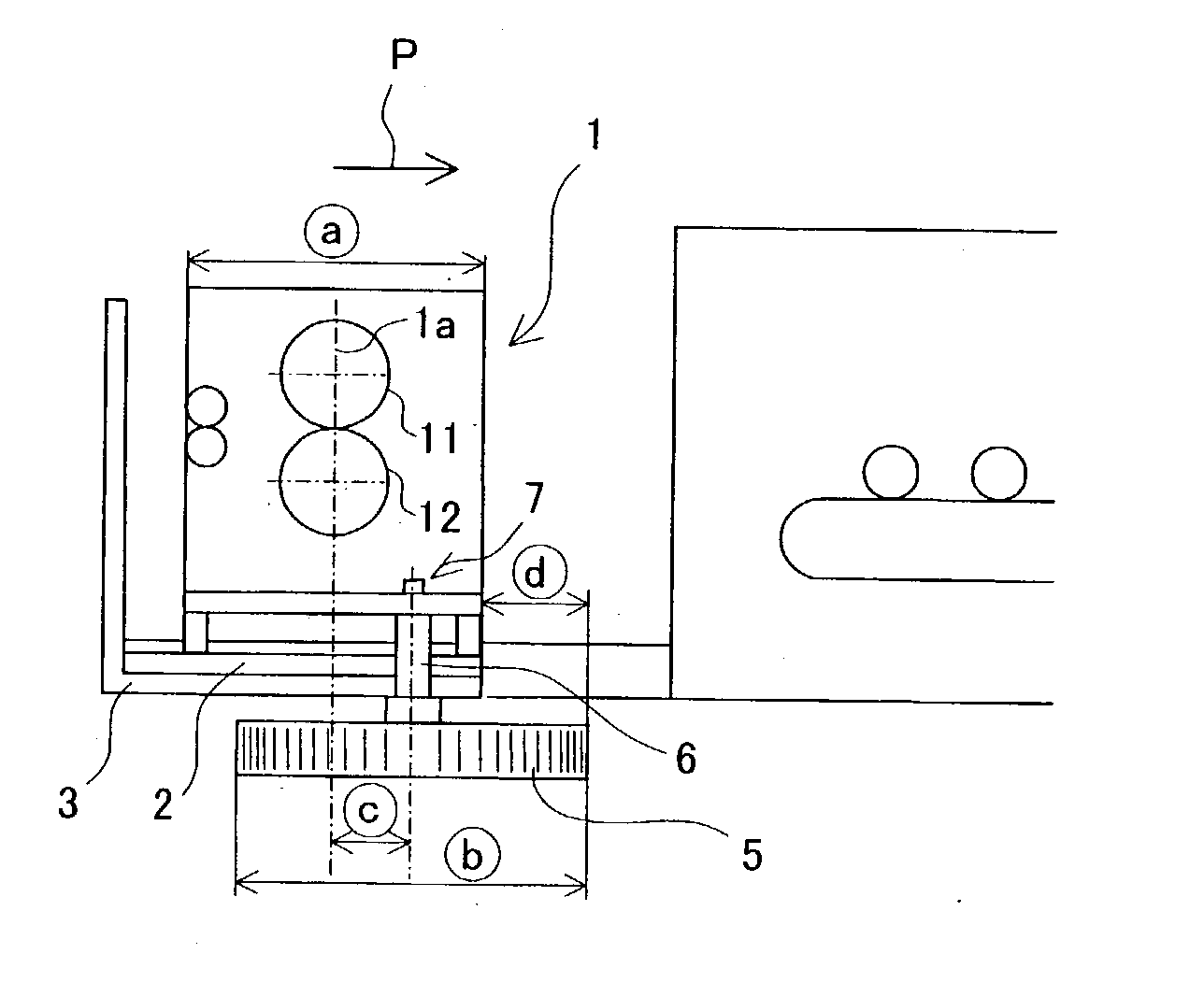
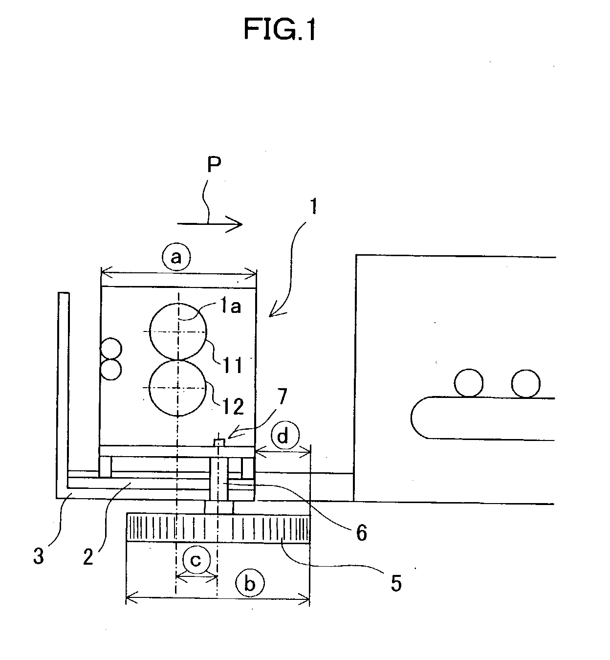
[0029] FIG. 1 is a diagram showing a state in which a base plate 2 supporting a fuser unit (customer replaceable functional unit) 1 has been drawn out to one side (left side as illustrated) of the image forming apparatus for replacement of the fuser unit 1, for example. Front and rear ends of the base plate 2 lie on two guides 3 located parallel to each other close to front and rear sides of a housing (not shown in FIG. 1) of the image forming apparatus, respectively. In FIG. 1, the reference numeral 11 designates a heating roller and the reference numeral 12 designates a pressure roller.

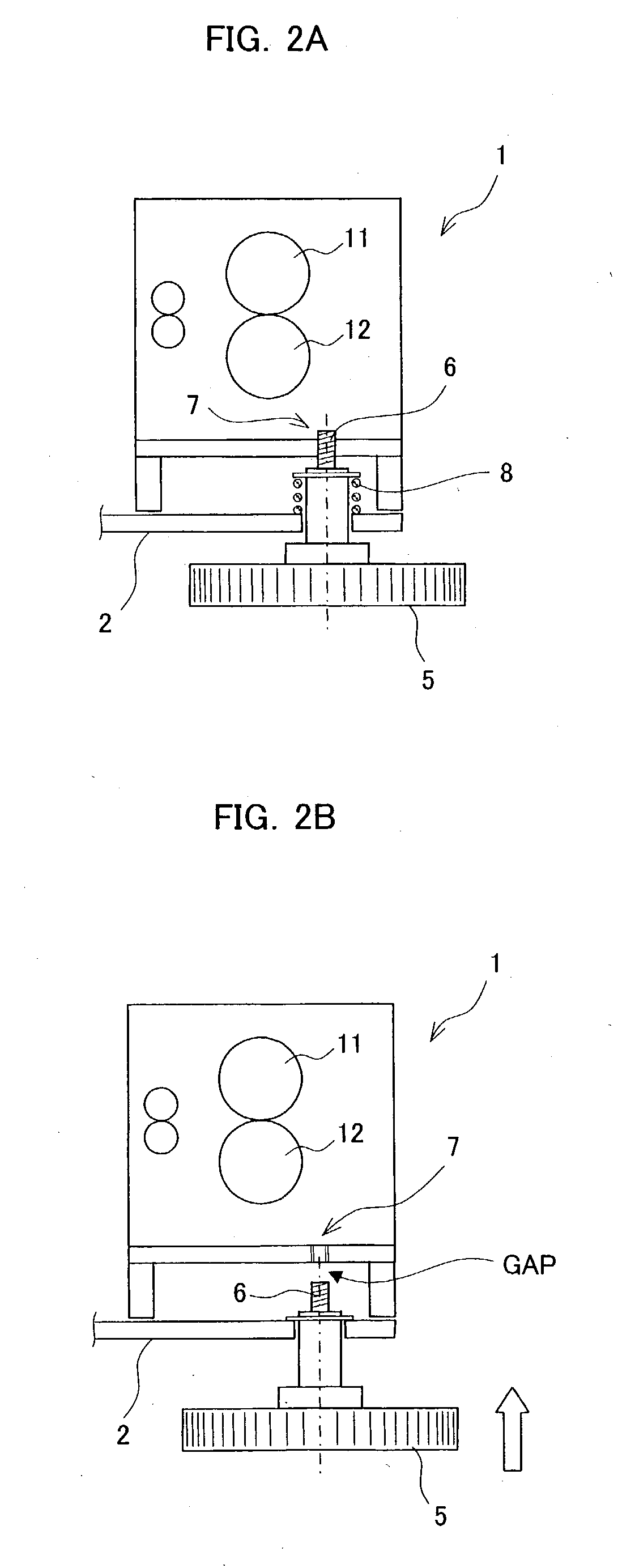
[0030] A far end of a threaded shaft 6 formed as an integral part of an operating device 5 i...


PUM


Abstract

A base plate detachably supports a functional unit all the way between an exposed position where the functional unit is separated from a connector and drawn out of a housing of an image forming apparatus such that the functional unit is exposed to the exterior of the housing and an accommodated position where the functional unit is fitted in the housing and connected to the connector. A biasing member biases a threaded shaft of an operating device through the base plate such that a far end of the threaded shaft is directed toward a threaded hole formed in the bottom of the functional unit. The operating device is hidden inside the housing of the apparatus when the base plate is set to the accommodated position.

Description

[0001] 1. Field of the Invention[0002] The present invention relates to a support mechanism for detachably supporting a fixing unit (fuser unit) or other functional units of an image forming apparatus, such as a copy machine, inside the apparatus, as well as to an image forming apparatus employing such a support mechanism.[0003] 2. Description of the Related Art[0004] A copy machine, a conventionally known example of an image forming apparatus, works as follows. As shown in FIG. 5, an original document (not shown) placed on platen glass 21 is scanned by an optical unit 22 to produce a latent image corresponding to an image on the document on a photosensitive drum 23. A developing unit 24 convert the latent image into a visual image through an electrostatic process.[0005] The visual image thus produced is transferred onto a sheet of copying paper (not shown) fed from a paper cassette 26 and fused, or fixed, onto the copying paper by a fuser unit 26. A final copy is then discharged fr...

Claims


Application Information

Patent Timeline
IPC IPC(8): B41J29/00F16C13/02G03G15/20G03G21/16G03G21/18
CPCG03G21/1842G03G21/1685G03G2221/1684
Inventor MIKITA, TOSHIYATATEISHI, YOSHINOBUMINAKUCHI, YASUNORIMATSUYAMA, KAZUHIROIDE, ATSUSHIYAMANAKA, TOSHIO
Owner SHARP KK
Why Eureka
Try Eureka