

Servo control device
- Summary
- Abstract
- Description
- Claims
- Application Information
AI Technical Summary
Benefits of technology
Problems solved by technology
Method used
Image

Examples
Embodiment Construction
[0042] Some embodiments of the invention will now be explained below with reference to the drawings.
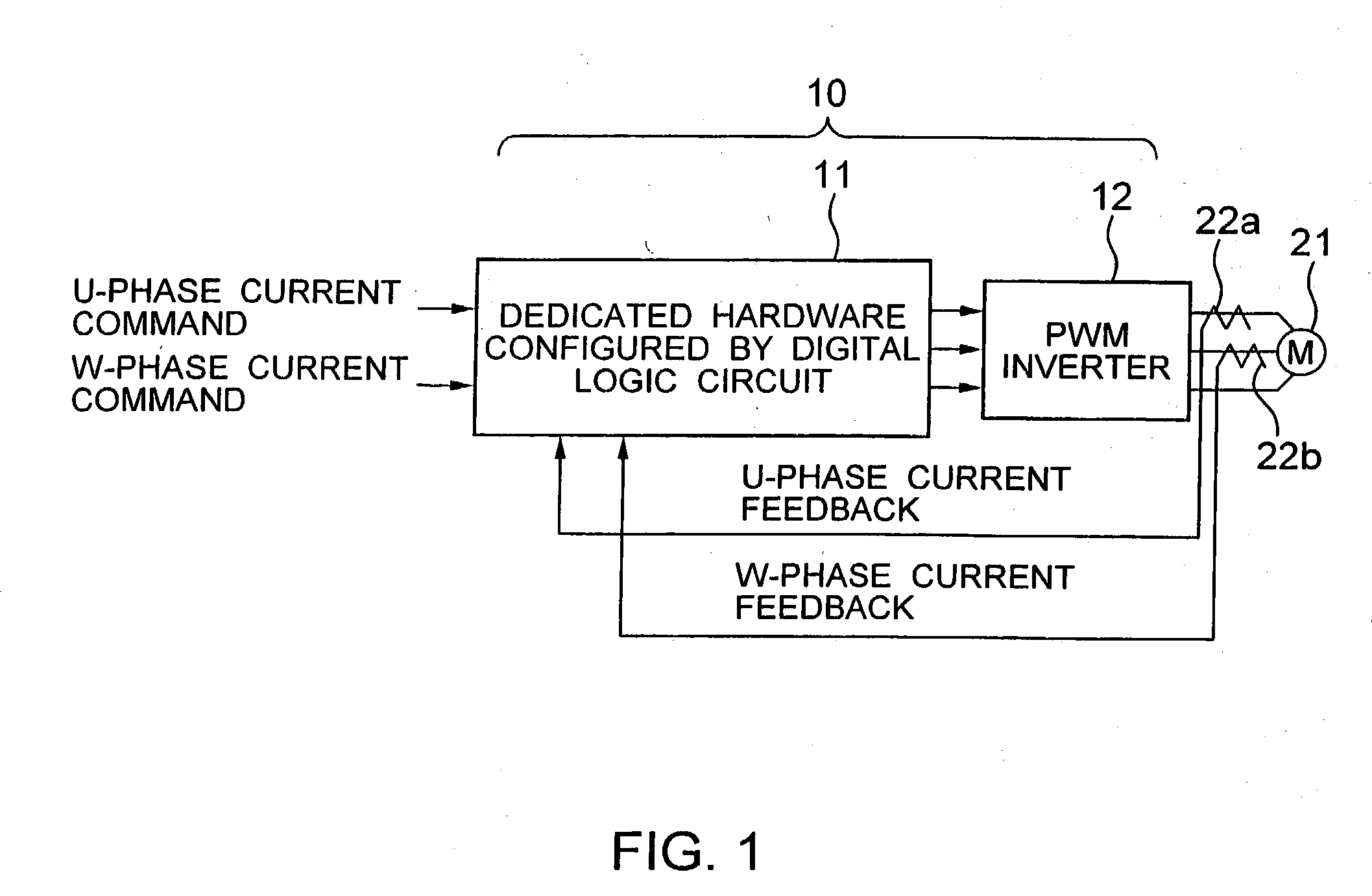
[0043] FIG. 1 is a schematic block diagram showing a servo control device 10 according to an embodiment of the invention. As shown in FIG. 1, the servo control device 10 is connected to a synchronous motor 21 to control the current thereof. In association with the synchronous motor 21, current detectors 22a, 22b are connected to detect the current of the motor 21.
[0044] The servo control device 10 includes a digital logic circuit 11 supplied with external current commands (U-phase current command and W-phase current command), and a PWM inverter 12 that supplies the synchronous motor 21 with a power for rotating it on the basis of the command value output from the digital logic circuit 11.
[0045] The digital logic circuit 11 is configured to output to the PWM inverter 12 a command value reducing to zero the difference between current command (command value) and a current value (feedback...
PUM
| Property | Measurement | Unit |
|---|---|---|
| Angle | aaaaa | aaaaa |
| Speed | aaaaa | aaaaa |
| Current | aaaaa | aaaaa |
Abstract
Description
Claims
Application Information